Ceramic atomization core and preparation method thereof

A technology of atomizing core and ceramics, which is applied in the field of atomizers, can solve the problems of limited application range, easy oxidation of stainless steel tubes, and high thermal conductivity, etc., and achieves a simple and efficient preparation method, which is conducive to industrial production and convenient operation and control. Effect

Pending Publication Date: 2021-09-07
东莞市国研精瓷电子有限公司
View PDF0 Cites 7 Cited by
  • Summary
  • Abstract
  • Description
  • Claims
  • Application Information

AI Technical Summary

Problems solved by technology

[0002] At present, most of the atomizing cores used in electronic cigarette atomizers are porous ceramic heating elements, which mainly adopt the process of integrally forming metal heating wires and porous ceramic substrates. Cotton consistency is unstable, low efficiency; low temperature sintering, stainless steel tubes are easy to oxidize
[0003] In addition, the porous ceramic heating elements currently used in e-liquids are inlaid with resistance heating wires or printed heating lines on the ceramics. The heating depends on the resistance heating wires or printed lines. Complicated and other defects. In addition, the existing porous ceramic substrates have fixed pore size and porosity, and the thermal conductivity is easy to be too high or too low. There is a problem that it is difficult to match the thermal conductivity and the atomization effect of the e-liquid. Low efficiency, limited strength and limited range of use

Method used


Image

  • Ceramic atomization core and preparation method thereof
  • Ceramic atomization core and preparation method thereof
  • Ceramic atomization core and preparation method thereof

Examples


Embodiment 1

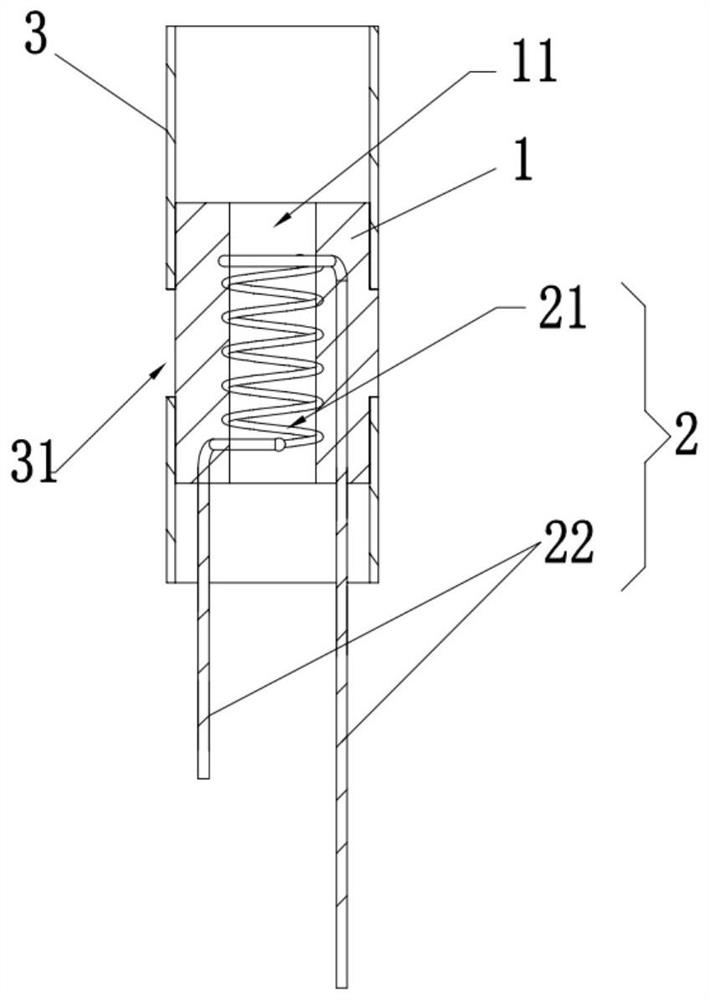
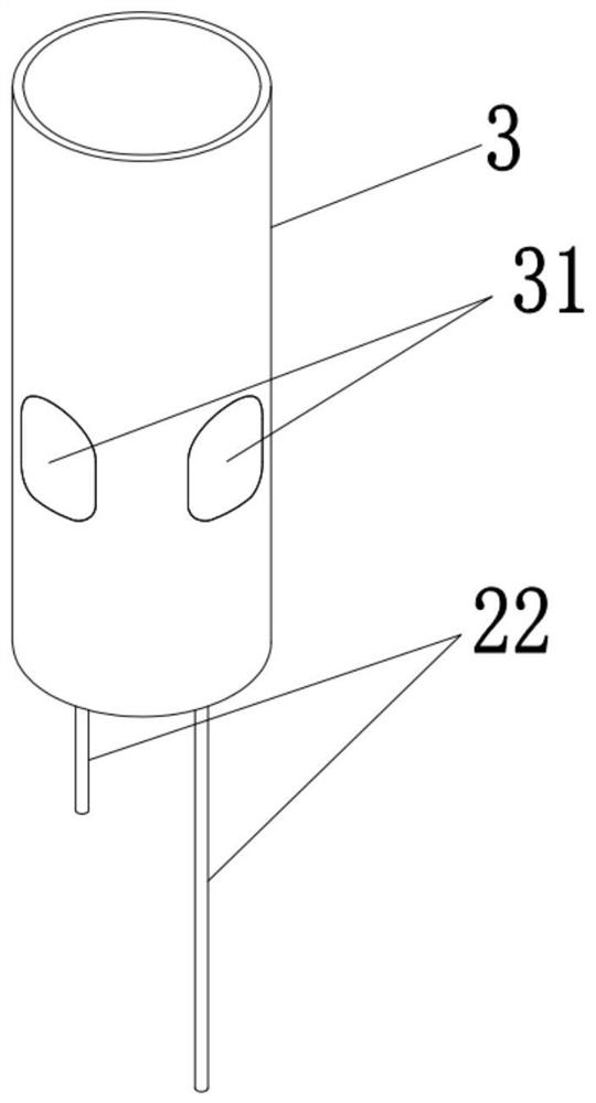
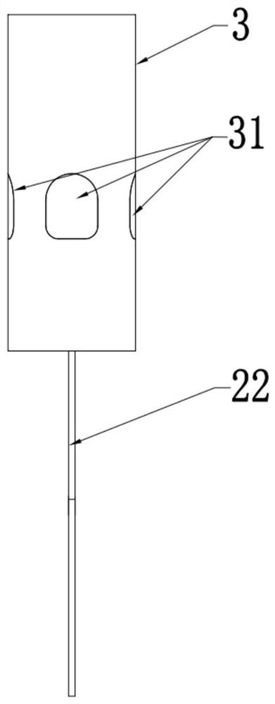
[0042] A ceramic atomizing core, a porous ceramic substrate 1, a heating component 2 and a stainless steel tube 3, the interior of the porous ceramic substrate 1 is provided with an air flow channel 11, and the air flow channel 11 runs through the upper surface and the lower surface of the porous ceramic substrate The side wall of the stainless steel tube 3 is provided with a plurality of oil inlet holes 31, the stainless steel tube 3 is sleeved on the outer wall of the porous ceramic substrate 1, the heating element 2 is embedded in the porous ceramic substrate 1 and Around the circumferential direction of the air flow channel 11, the end of the heating component 2 is provided with a heating wire extension 22, and the heating wire extension 22 protrudes out of the porous ceramic substrate 1, and the porous ceramic substrate 1 is composed of a porous It is made by sintering ceramic materials; the shell of the stainless steel tube 3 is silvery white, and the material of the stai...

Embodiment 2

[0063] A ceramic atomizing core, a porous ceramic substrate 1, a heating component 2 and a stainless steel tube 3, the interior of the porous ceramic substrate 1 is provided with an air flow channel 11, and the air flow channel 11 runs through the upper surface and the lower surface of the porous ceramic substrate The side wall of the stainless steel tube 3 is provided with a plurality of oil inlet holes 31, the stainless steel tube 3 is sleeved on the outer wall of the porous ceramic substrate 1, the heating element 2 is embedded in the porous ceramic substrate 1 and Around the circumferential direction of the air flow channel 11, the end of the heating component 2 is provided with a heating wire extension 22, and the heating wire extension 22 protrudes out of the porous ceramic substrate 1, and the porous ceramic substrate 1 is composed of a porous It is made by sintering ceramic materials; the shell of the stainless steel tube 3 is silvery white, and the material of the stai...

Embodiment 3

[0084] A ceramic atomizing core, a porous ceramic substrate 1, a heating component 2 and a stainless steel tube 3, the interior of the porous ceramic substrate 1 is provided with an air flow channel 11, and the air flow channel 11 runs through the upper surface and the lower surface of the porous ceramic substrate The side wall of the stainless steel tube 3 is provided with a plurality of oil inlet holes 31, the stainless steel tube 3 is sleeved on the outer wall of the porous ceramic substrate 1, the heating element 2 is embedded in the porous ceramic substrate 1 and Around the circumferential direction of the air flow channel 11, the end of the heating component 2 is provided with a heating wire extension 22, and the heating wire extension 22 protrudes out of the porous ceramic substrate 1, and the porous ceramic substrate 1 is composed of a porous It is made by sintering ceramic materials; the shell of the stainless steel tube 3 is silvery white, and the material of the stai...


PUM

PropertyMeasurementUnit
Meshaaaaaaaaaa
Meshaaaaaaaaaa
Meshaaaaaaaaaa

Abstract

The invention relates to the technical field of atomizers, in particular to a ceramic atomization core and a preparation method thereof. The ceramic atomization core comprises a porous ceramic substrate, a heating component and a stainless steel pipe. An air flow channel is formed in the porous ceramic base body, a plurality of oil inlet holes are formed in the side wall of the stainless steel pipe, and the stainless steel pipe is arranged on the outer wall of the porous ceramic substrate in a sleeving mode. The heating component is embedded in the porous ceramic substrate and is wound in the circumferential direction of the air flow channel, the end part of the heating component is provided with a heating wire extending part, the heating wire extending part protrudes out of the porous ceramic substrate, and the porous ceramic substrate is prepared by sintering a porous ceramic material. The ceramic atomization core is novel in structure, ceramic oil absorption is fast, the ceramic atomization core makes direct contact with tobacco tar, heat conduction is faster, smoke flows out through the air flow channel after being heated and atomized through the porous ceramic substrate, and the atomization efficiency of the ceramic atomization core is improved; and the ceramic atomizing core does not need manual cotton wrapping, and is convenient to assemble, high in production efficiency, high in practicability, energy-saving, safe and environment-friendly.

Description

technical field [0001] The invention relates to the technical field of atomizers, in particular to a ceramic atomizing core and a preparation method thereof. Background technique [0002] At present, most of the atomizing cores used in electronic cigarette atomizers are porous ceramic heating elements, which mainly adopt the process of integrally forming metal heating wires and porous ceramic substrates. Cotton consistency is unstable, low efficiency; low temperature sintering, stainless steel tubes are easy to oxidize. [0003] In addition, the porous ceramic heating elements currently used in e-liquids are inlaid with resistance heating wires or printed heating lines on the ceramics. The heating depends on the resistance heating wires or printed lines. Complicated and other defects. In addition, the existing porous ceramic substrates have fixed pore size and porosity, and the thermal conductivity is easy to be too high or too low. There is a problem that it is difficult t...

Claims


Application Information

Patent Timeline
IPC IPC(8): A24F40/46A24F40/70C04B38/06C04B35/14
CPCA24F40/46A24F40/70C04B38/068C04B38/067C04B38/0645C04B35/14C04B2235/3217C04B2235/3826
Inventor 李伟张跃朋曾道友
Owner 东莞市国研精瓷电子有限公司
Why Eureka
Try Eureka