Detachable chair leg and assembling method thereof

A chair foot and foot piece technology, applied in the field of detachable chair feet and their assembly, can solve the problems of inconvenient assembly and disassembly operations, high transportation and storage costs, low tool efficiency, etc., so as to save transportation and storage costs and ensure accurate performance and improve assembly efficiency

Active Publication Date: 2021-09-07
安吉史博家具股份有限公司
View PDF11 Cites 0 Cited by
  • Summary
  • Abstract
  • Description
  • Claims
  • Application Information

AI Technical Summary

Problems solved by technology

[0005] Although the one-piece injection molded chair legs have the above advantages, this kind of chair legs has the following defects: when the chair legs are packaged, they will occupy a large space volume, resulting in high transportation and storage costs and unreasonable design
[0006] Secondly, there are some chair legs that are connected to each other. Although this method has the advantage of being detachable, this method of socketing is not conducive to assembly. After assembly, additional screws are required for fixing, and the efficiency of using tools is low. And it is inconvenient to assemble and disassemble

Method used


Image

  • Detachable chair leg and assembling method thereof
  • Detachable chair leg and assembling method thereof
  • Detachable chair leg and assembling method thereof

Examples


Embodiment 1

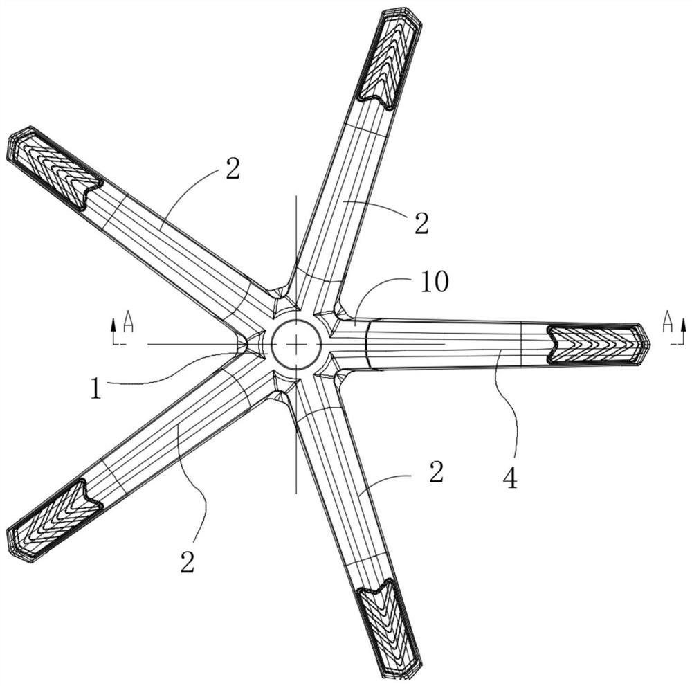
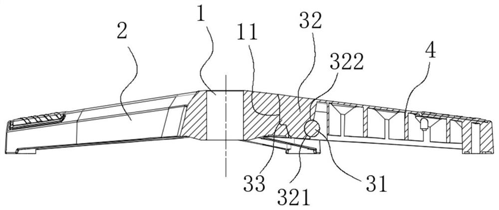
[0043] Such as figure 1 As shown, the detachable chair foot includes several integral foot pieces 2 integrally injection-molded with the center base 1, and a detachable foot piece 4 connected with the center base 1 through a rotating assembly connection mechanism 3, as Figure 5 As shown, the transverse section of the detachable foot piece 4 is U-shaped, and in order to improve the structural strength, a reinforcing rib 43 is provided in the U-shaped groove of the detachable foot piece 4 .

[0044] There are four integrated foot pieces 2, and the detachable foot pieces 4 and the integrated foot pieces 2 are evenly distributed around the circumference for supporting purposes.

[0045] The center of the center seat 1 is provided with a vertical shaft hole to facilitate the assembly of the seat cushion shaft.

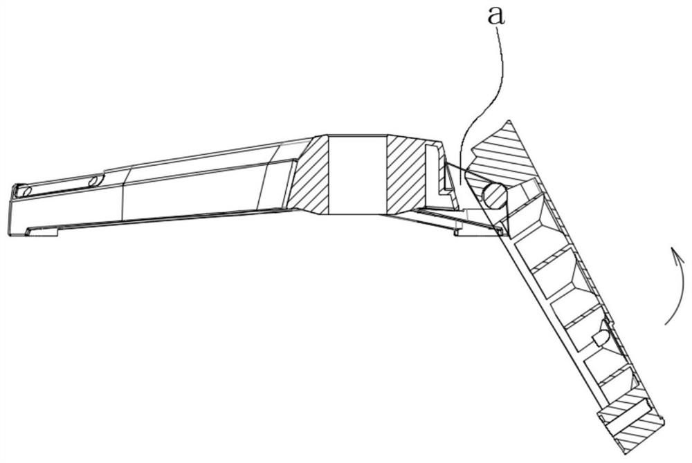
[0046] Such as Figure 2-Figure 7 As shown, the described rotary assembly connection mechanism 3 includes:

[0047] The radial support arm 30 is connected with the cent...

Embodiment 2

[0081] Such as figure 1 and Figure 9 As shown, a wheeled chair foot has the detachable chair foot described in Embodiment 1, and a roller 5 installed on the lower side of the outer end of the integral leg 2 and the detachable leg 4 .

Embodiment 3

[0083] A swivel chair has the roller chair foot described in the second embodiment, and a seat cushion assembly and a backrest assembly installed on the roller chair foot.


PUM


Abstract

The invention belongs to the technical field of chair legs, and particularly relates to a detachable chair leg and an assembling method thereof. The technical problem that an existing chair leg is not easy to disassemble and assemble is solved. The detachable chair leg comprises a plurality of integrated leg parts and at least one detachable leg part, the integrated leg parts and a center seat are integrally formed in an injection molding mode, the detachable leg parts are connected with the center seat through a rotary assembling and connecting mechanism, and the rotary assembling and connecting mechanism comprises a radial supporting arm which is connected with the center seat and extends outwards in the radial direction of the center seat; the rotary assembling and connecting mechanism comprises a rotary connecting shaft ; the rotary connecting shaft is connected to the radial supporting arm, and the axis of the rotary connecting shaft is transversely distributed; the rotary assembling and connecting mechanism comprises a rotary assembly anti-tripping buckle; the rotary assembly anti-tripping buckle is connected to the inner end, close to the center seat, of the detachable leg part; and when the rotary assembly anti-tripping buckle rotates in place, the rotary assembly anti-tripping buckle and the rotary connecting shaft enable the detachable leg part to be axially locked relative to the central seat. The device has the advantages that the device is easy to assemble and disassemble, the occupied space is saved, and the transportation and storage cost is reduced.

Description

technical field [0001] The invention belongs to the technical field of chair legs, in particular to a detachable chair leg and an assembly method thereof. Background technique [0002] The chair foot is used for the bottom support of the chair. [0003] The chair legs have rolling chair legs and non-rolling chair legs, and at the same time, metal and non-metal chair legs are also available. [0004] Its chair foot of existing swivel chair is generally processed and manufactured by metal and nonmetal material. In particular, the non-metallic chair legs are generally made of plastic material, and five one-legged chair legs are integrally formed by injection molding, which has high efficiency and good structural strength. [0005] Although the integrated injection-molded chair legs have the above advantages, such chair legs have the following defects: when the chair legs are packaged, they will occupy a larger space volume, resulting in higher transportation and storage costs...

Claims


Application Information

Patent Timeline
Patent Type & Authority Applications(China)
IPC IPC(8): A47C7/00A47C4/02
CPCA47C7/006A47C7/002A47C4/02
Inventor 王超
Owner 安吉史博家具股份有限公司
Why Eureka
Try Eureka