Device and method for promoting rapid dissolution of chemical agent for oil displacement
A chemical agent and oil displacement agent technology, which is applied in the field of devices to promote the rapid dissolution of oil displacement chemical agents, and can solve the problems that the rapid dissolution and constant temperature dissolution of oil displacement agents cannot be realized.
- Summary
- Abstract
- Description
- Claims
- Application Information
AI Technical Summary
Problems solved by technology
Method used
Image
Examples
Embodiment 1
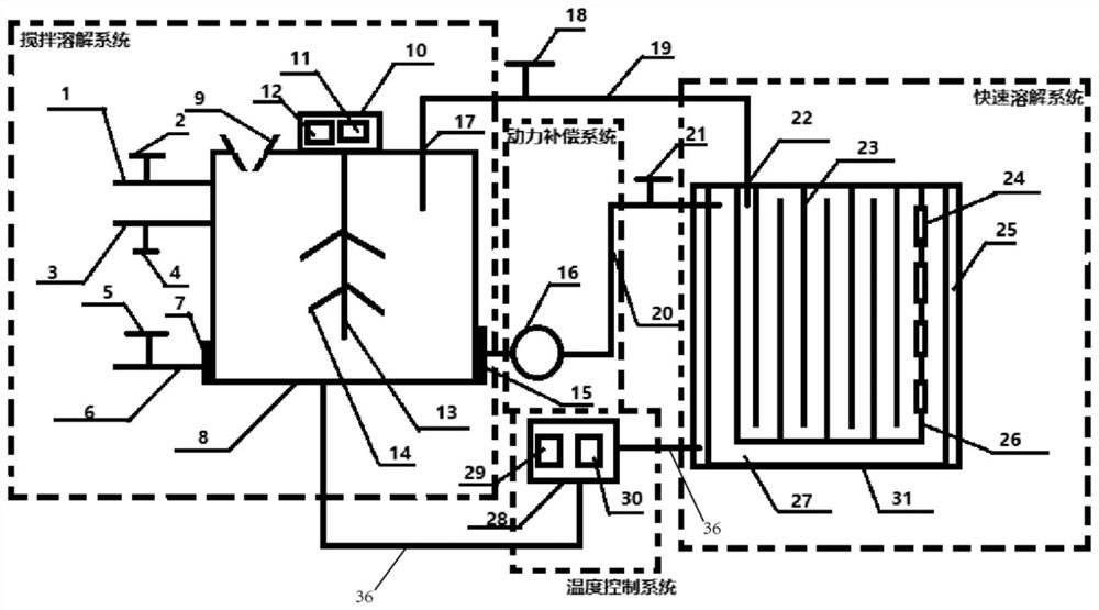
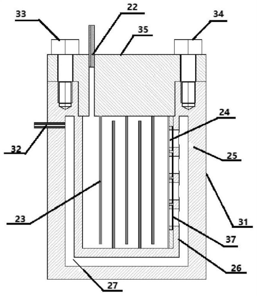
[0037] A device for promoting the rapid dissolution of chemical agents for oil displacement, including a stirring and dissolving system, a rapid dissolving system, a temperature control system and a power compensation system,
[0038] The stirring and dissolving system includes a stirring tank 8, a stirring device and a stirring heating device. A stirring device is arranged in the middle of the top of the stirring tank 8, and a solid oil displacing agent feeding port 9 and a circulation inlet 17 are respectively arranged on both sides of the stirring device. The upper part of the tank is provided with a liquid oil displacement agent input pipeline 1 and a liquid distribution water input pipeline 3 in sequence from top to bottom, and a liquid outlet pipeline 6 and a circulating liquid outlet pipeline 20 are respectively arranged on the left and right sides of the lower part of the stirring tank 8 , the stirring and heating device is sleeved outside the stirring tank 8;
[0039] T...
Embodiment 2
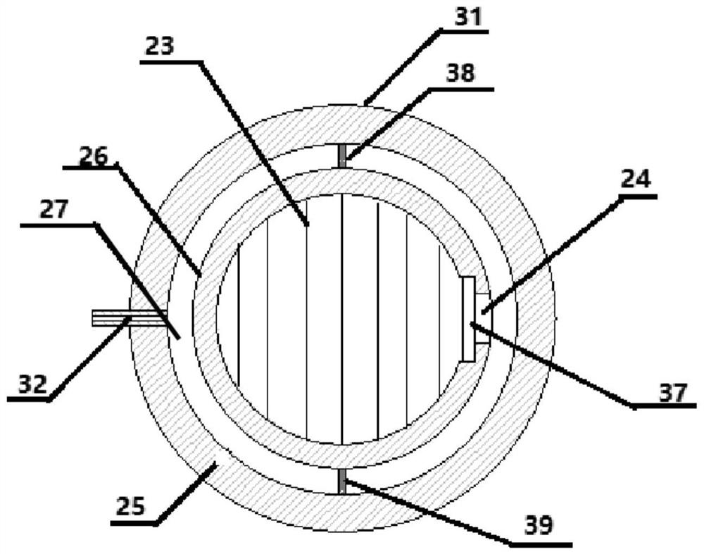
[0043] On the basis of Embodiment 1, a first inner cavity baffle 38 and a second inner cavity baffle 39 are also arranged on the top cover between the inner container 26 and the outer container 31, the first inner cavity baffle 38 and the second inner cavity baffle Two inner cavity baffles 39 are respectively installed in the middle part of the inner cavity 27 between the liquid circulation inlet 32 and the inner inlet 24, the movable ends of the first inner cavity baffle 38 and the second inner cavity baffle 39 are in contact with the outer bladder. The vertical distance between them is 8-12cm.
[0044] The inner inlet 24 is arranged in parallel with the baffle plate 23, the quantity of the inner inlet 24 is 4, the width of the inner inlet 24 is 12-18cm, and the inner inlet filter screen 37 is fixed at the inner inlet 24, which is used for filtering the chemical agent for oil displacement formed crystals.
[0045] The quantity of baffle plate 23 is 7, and the vertical dist...
Embodiment 3
[0048] On the basis of embodiment two, the stirring device comprises a stirrer motor 10, a stirring speed regulator 11, a stirring speed display 12, a stirring rod 13 and a stirring paddle 14, and the stirring motor 10 is installed in the top middle part of the stirring tank 8, and the stirring motor 10 The output shaft is connected to the head end of the stirring rod 13, the tail end of the stirring rod 13 extends into the stirring tank 8, and the stirring paddle 14 is staggered and fixed at the middle and lower part of the stirring rod 13, the stirring speed regulating device 11 is connected with the stirring motor 10, and the stirring The speed display 12 is used for displaying the real-time stirring speed of the stirring speed regulating device 11 .
[0049] The number of stirring paddles 14 is four, and the range of the stirring speed adjusted by the stirring speed regulating device 11 is 0-200r / min.
[0050] A liquid outlet filter 7 is fixed on the outlet pipeline 6 for ...
PUM
 Abstract
Description
Claims
Application Information
 - R&D
- Intellectual Property
- Life Sciences
- Materials
- Tech Scout
- Unparalleled Data Quality
- Higher Quality Content
- 60% Fewer Hallucinations
Browse by: Latest US Patents, China's latest patents, Technical Efficacy Thesaurus, Application Domain, Technology Topic, Popular Technical Reports.
© 2025 PatSnap. All rights reserved.Legal|Privacy policy|Modern Slavery Act Transparency Statement|Sitemap|About US| Contact US: help@patsnap.com


