Die structure capable of automatically centering and laterally stamping inner hole of casting

An automatic centering and side stamping technology, which is applied in the direction of piercing tools, manufacturing tools, metal processing, etc., can solve problems such as low yield, relative position deformation or offset, product scrapping, etc.

Pending Publication Date: 2021-09-07
灏昕汽车零部件制造无锡有限公司
View PDF0 Cites 0 Cited by
  • Summary
  • Abstract
  • Description
  • Claims
  • Application Information

AI Technical Summary

Problems solved by technology

[0003] Most of the inner hole skins of the die-casting parts in the die-casting process are removed through the subsequent trimming and punching process. Because the draining system of the die-casting parts is affected by thermal expansion and contraction, the relative position of the die-casting parts will be deformed or Offset, the position of the inner hole of the die casting will deviate after it is placed on the punching die. The side punch of the conventional punching die structure will cut the surface of the inner hole due to the deviation of the inner hole, but the inner hole of the die casting often has High-precision requirements, once cut by the punch will directly lead to product scrapping, so the yield of this process is low, and the proportion of rework and scrapping is high

Method used


Image

  • Die structure capable of automatically centering and laterally stamping inner hole of casting
  • Die structure capable of automatically centering and laterally stamping inner hole of casting
  • Die structure capable of automatically centering and laterally stamping inner hole of casting

Examples


Embodiment Construction

[0019] The following will clearly and completely describe the technical solutions in the embodiments of the present invention with reference to the accompanying drawings in the embodiments of the present invention. Obviously, the described embodiments are only some, not all, embodiments of the present invention.

[0020] In the description of the present invention, unless otherwise stated, the meaning of "plurality" is two or more; the terms "upper", "lower", "left", "right", "inner", "outer" , "front end", "rear end", "head", "tail", etc. indicate the orientation or positional relationship based on the orientation or positional relationship shown in the drawings, and are only for the convenience of describing the present invention and simplifying the description, rather than Nothing indicating or implying that a referenced device or element must have a particular orientation, be constructed, and operate in a particular orientation should therefore not be construed as limiting ...


PUM


Abstract

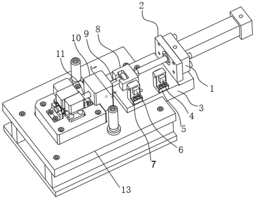
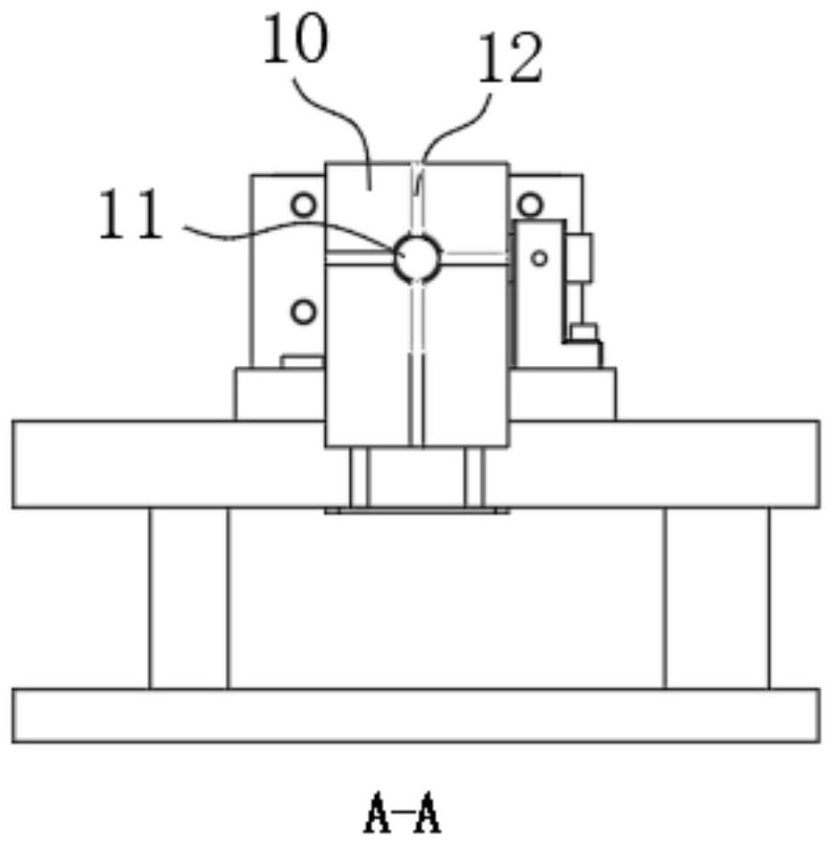
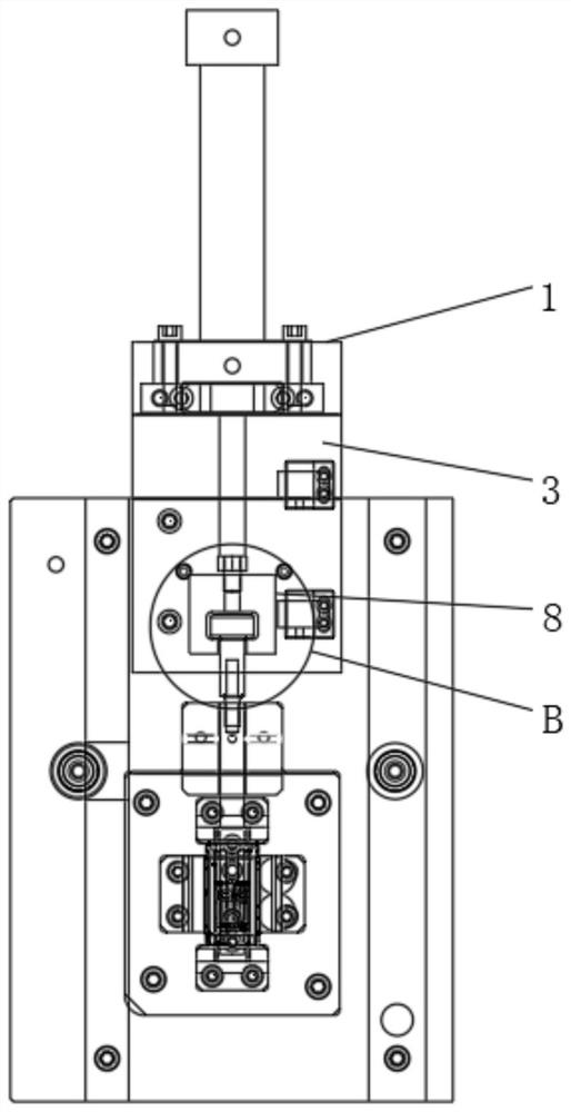
The invention relates to a die structure capable of automatically centering and laterally stamping an inner hole of a casting, which comprises an oil cylinder and an oil cylinder joint; the end part of the oil cylinder is fixedly connected with an oil cylinder flange through a screw, and the end part of the oil cylinder flange is provided with an oil cylinder fixing seat; a rear-position sensor fixing seat and a front-position sensor fixing seat are fixed to one side wall of the upper end of the oil cylinder fixing seat; a rear-position sensor is arranged at the upper end of the rear-position sensor fixing seat; and a front-position sensor is installed at the upper end of the front-position sensor fixing seat. The die structure capable of automatically centering and laterally stamping the inner hole of the casting provided by the invention has the beneficial effects that through movement of a punch fixing block and a punching punch, the structure positions of the punching punch and a punching part at the front end of the punching punch can be adjusted, an arc-shaped notch is arranged at the middle of the upper end wall of a floating joint, a movable spring plunger is clamped into the arc-shaped notch arranged at the middle of the upper end wall of the floating joint, and freedom degree limiting operation is conducted on the floating joint.

Description

technical field [0001] The invention relates to the technical field of molds, in particular to a mold structure capable of automatically centering the inner hole of a side stamping casting. Background technique [0002] Mold (mújù), various molds and tools used in industrial production for injection molding, blow molding, extrusion, die-casting or forging forming, smelting, stamping and other methods to obtain the required products. In short, a mold is a tool used to make shaped objects. This tool is composed of various parts, and different molds are composed of different parts. [0003] Most of the inner hole skins of the die-casting parts in the die-casting process are removed through the subsequent trimming and punching process. Because the draining system of the die-casting parts is affected by thermal expansion and contraction, the relative position of the die-casting parts will be deformed or Offset, the position of the inner hole of the die casting will deviate after...

Claims


Application Information

Patent Timeline
Patent Type & Authority Applications(China)
IPC IPC(8): B21D28/34B21C51/00
CPCB21D28/34B21C51/00
Inventor 魏忠江海峰李波
Owner 灏昕汽车零部件制造无锡有限公司
Why Eureka
Try Eureka