
Special equipment for welding steel components

A special device and component technology, which is applied in the field of special welding devices for section steel components, can solve the problems of reducing the work efficiency of operators, prone to bumps, and increasing the work process of operators, so as to improve operability and convenience, improve positioning effectiveness, The effect of increasing flexibility

Active Publication Date: 2022-05-03
JIANGSU WANXIANG CONSTR ENG GRP CO LTD
View PDF6 Cites 0 Cited by
  • Summary
  • Abstract
  • Description
  • Claims
  • Application Information

AI Technical Summary

Problems solved by technology

[0003] In the current H-shaped steel processing and welding process, the web and the flange are generally welded and combined to form an H-shaped steel body. However, it is difficult to position the web before it is combined with the flange plate, which increases the difficulty and inconvenience of the staff. Moreover, it is difficult to maintain a good fixing effect between the flange plate and the web after positioning, and it is easy to cause position deviation during the welding process, resulting in an increase in the processing error of the H-shaped steel frame and reducing the accuracy and pass rate of the steel welding; during the processing and welding of the H-shaped steel , it is difficult for the welding head of the welding torch to correspond to the welding joint between the web and the flange plate, and it is not easy to maintain a balance to carry out welding seam splicing at the joint of the section steel, which reduces the difficulty of welding the H-section steel components and reduces the work efficiency of the operator. During the welding of section steel, it is often necessary to turn over the whole welded H-section steel on one side before welding the other side. The existing overturning operation generally lifts and turns the H-section steel by a sling, which not only makes the H-section steel It is difficult to maintain balance when lifting, and it is prone to damage such as knocking, and the operation often involves repeated contact with the positioning of the H-shaped steel, which increases the workflow of the operator and reduces the welding efficiency of the steel components.

Method used


Image

  • Special equipment for welding steel components
  • Special equipment for welding steel components
  • Special equipment for welding steel components

Examples


Embodiment 1

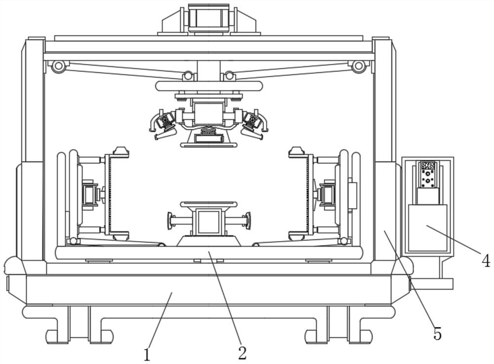
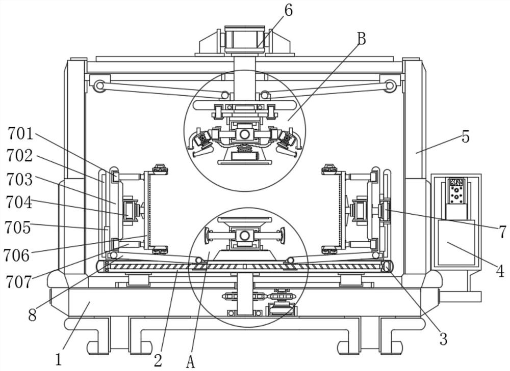
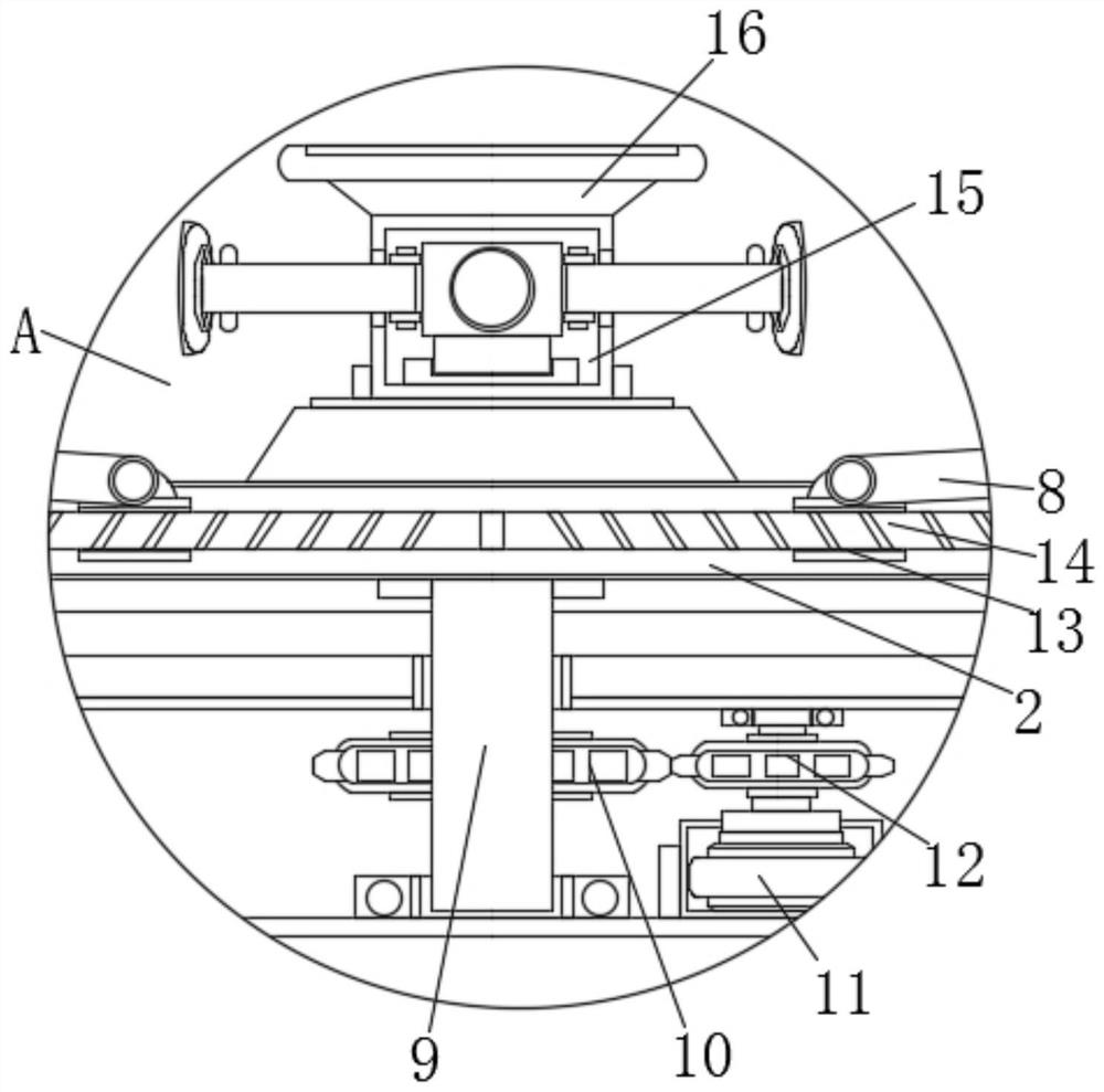
[0039] Example 1, such as Figure 1-2 As shown, during the welding work of the section steel, the servo motor B11 can be started through the console 4 to drive the driving gear 12 to rotate, forcing the driving gear 12 and the driven gear 10 to mesh with each other to drive the rotating column 9 to rotate as a whole, and prompting the rotating column 9 to drive the fixed plate 2. Under the cooperation of the ring guide rail and the guide block, it rotates around, and then adjusts the angle of the fixed plate 2 as a whole, and changes the position of the welded steel on the fixed plate 2. The operator can adjust the position suitable for the operation, which is convenient for the operator to observe. , to increase the flexibility of device use.

Embodiment 2

[0040] Example 2, such as Figure 1-2 As shown, after the welding of one side of the web and the flange plate is completed, the servo motor A3 and the rotating motor 7 can be started through the console 4, and the two-way screw rod A14 is driven to rotate by the start of the servo motor A3, and the two-way screw rod A14 The rotation of the two groups of internally threaded tubes A13 is driven away from each other, and drives the hinged support plate 8 to move and expand, forcing the hinged support plate 8 to lift the annular chute 703 under the cooperation of the guide block 705 and the guide plate 702. At this time, the The start of the rotating motor 7 drives the connecting frame to rotate 180° under the sliding of the slider 701 and the annular chute 703, turning over the H-shaped steel as a whole, and then turning over the servo motor A3 to allow the hinged support plate 8 to be accommodated, and clamping the H-shaped steel again , to perform welding operation on the other...

Embodiment 3

[0041] Example 3, such as Figure 4 As shown, during welding when the welding torch 19 moves horizontally under the cooperation of the electromagnetic guide rail 21 and the electromagnetic guide block 20, the suction fan 17 can be started through the console 4, and the telescopic tube 172 and the flow guide tube 173 of the suction fan 17 in the telescopic state can be used. Under the connection and cooperation, the slag inclusions and dust that appear in the welding of the welding torch 19 are absorbed under the corresponding suction port 174, so that the residue is automatically collected into the collection tank 171, with subsequent cleaning, the automatic dust collection effect of the welding work of the device is increased, and the welding process is improved. Accuracy and convenience of follow-up cleaning work.

[0042] Working principle: when the device is in use, first place the web flat on the bearing of the positioning platform 16, and use the console 4 to start the e...


PUM


Abstract

The invention discloses a special welding device for section steel members, which includes a mounting seat, a rotating column is sleeved at the middle position of the inner bottom of the mounting seat, a driven gear is provided at the middle position outside the rotating column, and a driven gear is arranged inside the mounting seat. The side of the bottom near the rotating column is provided with a servo motor B, and the output end of the servo motor B is provided with a driving gear that meshes with the driven gear; The web is fit and clamped, and as the two sets of clamping discs approach each other, the flange plates combined with the web are fitted correspondingly, so that the flange plates are well in contact with the web and positioned. The welding work can be carried out through the welding torch, and at the same time cooperate with the expansion of the positioning plate to fit the bottom of the two sets of flange plates again to form an auxiliary support. Through the multi-directional clamping and positioning structure, the contact between the flange plate and the web plate is further improved targeting performance.

Description

technical field [0001] The invention relates to the technical field of steel structure welding, in particular to a special device for welding steel components. Background technique [0002] Sectional steel is a bar-shaped steel with a certain cross-sectional shape and size. It is one of the four major types of steel. According to the cross-sectional shape, section steel is divided into simple section section steel and complex section section steel. The former refers to square steel, round steel, flat steel, angle steel, Hexagonal steel, etc.; the latter refers to I-beam, channel steel, rail, window frame steel, curved steel, etc. In the processing of section steel, welding is one of the common processing methods. [0003] In the current H-shaped steel processing and welding process, the web and the flange are generally welded and combined to form an H-shaped steel body. However, it is difficult to position the web before it is combined with the flange plate, which increases...

Claims


Application Information

Patent Timeline
Patent Type & Authority Patents(China)
IPC IPC(8): B23K31/02B23K37/00B23K37/02B23K37/04B23K37/047B08B15/04
CPCB23K31/02B23K37/0443B23K37/0211B23K37/00B23K37/047B08B15/04
Inventor 曹兴进陈慧娟丁方杰陆军苏常银
Owner JIANGSU WANXIANG CONSTR ENG GRP CO LTD
Learn More