Brake caliper integrated with brake booster

A brake booster and brake caliper technology, which is applied in the direction of brakes, brake transmissions, transportation and packaging, etc., can solve problems such as limited installation space, high installation cost, and increased cost of pedal feel simulators. Effect

Pending Publication Date: 2021-09-07
ZHEJIANG LIBANG HEXIN INTELLIGENT BRAKING SYST CO LTD
View PDF5 Cites 0 Cited by
  • Summary
  • Abstract
  • Description
  • Claims
  • Application Information

AI Technical Summary

Problems solved by technology

At the same time, the market does not allow additional costs
The current passenger car braking system still uses brake fluid as the transfer material to transmit the braking demand to the wheel end calipers. Although the use of brake fluid has many advantages, it also brings a lot of problems to the current network layout of vehicles. Difficult, and has high installation cost and prone to parts wear or even damage for long-term use
In addition, in the prior art, fixed calipers tend to be selected to achieve better performance, but when using fixed calipers, the driving force should be transmitted to the outside of the calipers, and the installation space is very limited
[0003] The solution described in WO2021019380 solves the problem of electromechanical actuation of the fixed caliper, but it is not sufficient for the braking of service brakes
In addition, duplication of motors and transmissions results in considerable additional cost, and the resulting redundancy is difficult to fully utilize; EP1818235 attempts to reduce the complexity of the braking system by assigning an independent pressure building module to each caliper, thereby Reduce hydraulic network
However, since the pressure building module is separate from the caliper, it still needs to be installed, and if the brake fluid filling needs to be repeated for each wheel, the installation will be more complicated; The in

Method used


Image

  • Brake caliper integrated with brake booster
  • Brake caliper integrated with brake booster
  • Brake caliper integrated with brake booster

Examples


Embodiment

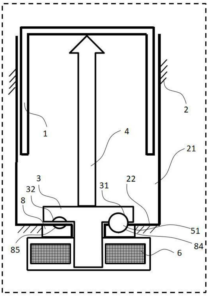
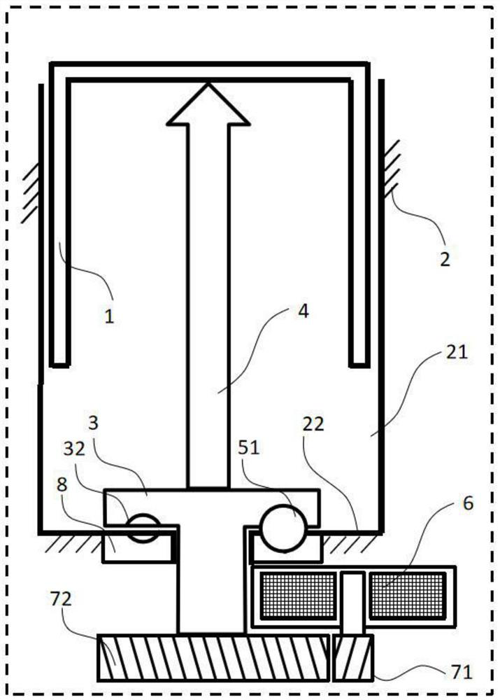
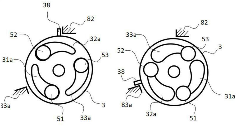
[0043] Such as figure 1 As shown, in the brake caliper, the caliper piston 1 is arranged in the brake cylinder 21 in the caliper body 2, and a single-cylinder, double-cylinder or even multi-cylinder pistons are integrated in the caliper for powering the caliper. This piston is generally called a wheel cylinder, and it can also be called a sub-cylinder. The ball ramp transmission mechanism is composed of a rotating member 3 provided with first arc surfaces 31, 32 and corresponding balls 51. A contact member 8 is fixed outside the clamp, and another second arc surface 84, 85 is formed inside the contact member 8. . The rotating member 3 is driven by a power source 6 to generate rotation, where the power source may be a motor or an element with a rotating bearing driven by a motor to rotate. When the rotating member 3 rotates, the rotation is converted into a linear motion of the rotating member through the mutual motion between the ball and the ramp, and this linear motion is ...


PUM


Abstract

The invention relates to the field of automobile braking, and particularly discloses a brake caliper integrated with a brake booster, the brake caliper comprises a caliper body and a brake cylinder arranged in the caliper body, a caliper piston, a transmission assembly and a rotating part are arranged in the brake cylinder, the transmission assembly comprises a pushing part capable of moving in the braking direction and pushing the caliper piston. A plurality of first cambered surfaces annularly arranged on the surface of the rotating part are arranged on at least one of the front side and the rear side of the rotating part, second cambered surfaces are arranged at the opposite positions of the first cambered surfaces, and balls are arranged between each pair of the first cambered surface and the second cambered surface; the ball is limited by the first cambered surface and the second cambered surface, can relatively slide along the ramp therein and drives the rotating piece to linearly move in the braking direction; the invention overcomes the limitations of the above solution by further reducing the need for hydraulic installation and the number of components, while retaining the possibility of arranging first-stage, second-stage or third-stage redundancy in the control device and without producing significant costs.

Description

technical field [0001] The invention relates to the field of automobile braking, in particular to a brake caliper integrated with a brake booster. Background technique [0002] Due to the increasing demand for higher performance and higher levels of autonomous driving in the whole vehicle, the brake system is required to develop in the direction of strengthening safety redundancy and reducing the cause of failure. At the same time, the market does not allow additional costs. The current passenger car braking system still uses brake fluid as the transfer material to transmit the braking demand to the wheel end calipers. Although the use of brake fluid has many advantages, it also brings a lot of problems to the current network layout of vehicles. It is difficult, and has high installation cost and is prone to wear or even damage to parts for long-term use. In addition, in the prior art, a fixed caliper tends to be selected to achieve better performance, but when using a fix...

Claims


Application Information

Patent Timeline
IPC IPC(8): B60T13/14
CPCB60T13/142B60T13/148
Inventor 巴洛赫·莱文特孙明海呙波白福利
Owner ZHEJIANG LIBANG HEXIN INTELLIGENT BRAKING SYST CO LTD
Why Eureka
Try Eureka