
Efficient sludge conditioning equipment

A sludge conditioning and high-efficiency technology, used in dewatering/drying/concentrating sludge treatment, mixers with rotary stirring devices, dissolving, etc. time, the effect of improving the contact area

Pending Publication Date: 2021-09-07
杭州国泰环保科技股份有限公司
View PDF4 Cites 0 Cited by
  • Summary
  • Abstract
  • Description
  • Claims
  • Application Information

AI Technical Summary

Problems solved by technology

[0002] Sludge is deposited in still water or slow flowing water environment, formed by physical, chemical and biochemical actions, unconsolidated soft fine-grained or very fine-grained soil, which belongs to modern recent sediments. When modern factories are performing production work, Sludge accumulation will also occur. In order to avoid environmental pollution and form a better living environment, sludge dehydration treatment is generally required in current technologies. In order to improve the dehydration rate, conditioners will be added in the prior art to improve pollution. The dehydration rate of mud treatment. In the process of adding conditioner, in order to improve the mixing rate of the agent in the prior art, the conditioner is directly put into the conditioning frame and the sludge is stirred. This structural design is used in the In the process, in order to ensure the mixing rate, it needs to be stirred for a long time, resulting in a long conditioning time and low efficiency. Therefore, we propose a high-efficiency sludge conditioning equipment

Method used


Image

  • Efficient sludge conditioning equipment
  • Efficient sludge conditioning equipment
  • Efficient sludge conditioning equipment

Examples


Embodiment Construction

[0023] In order to make the above objects, features and advantages of the present invention more comprehensible, specific implementations of the present invention will be described in detail below in conjunction with the accompanying drawings.

[0024] In the following description, a lot of specific details are set forth in order to fully understand the present invention, but the present invention can also be implemented in other ways different from those described here, and those skilled in the art can do it without departing from the meaning of the present invention. Similarly generalized, the present invention is therefore not limited by the specific embodiments disclosed below.

[0025] Secondly, the present invention is described in detail in combination with schematic diagrams. When describing the implementation of the present invention in detail, for the convenience of explanation, the cross-sectional view showing the device structure will not be partially enlarged accor...


PUM


Abstract

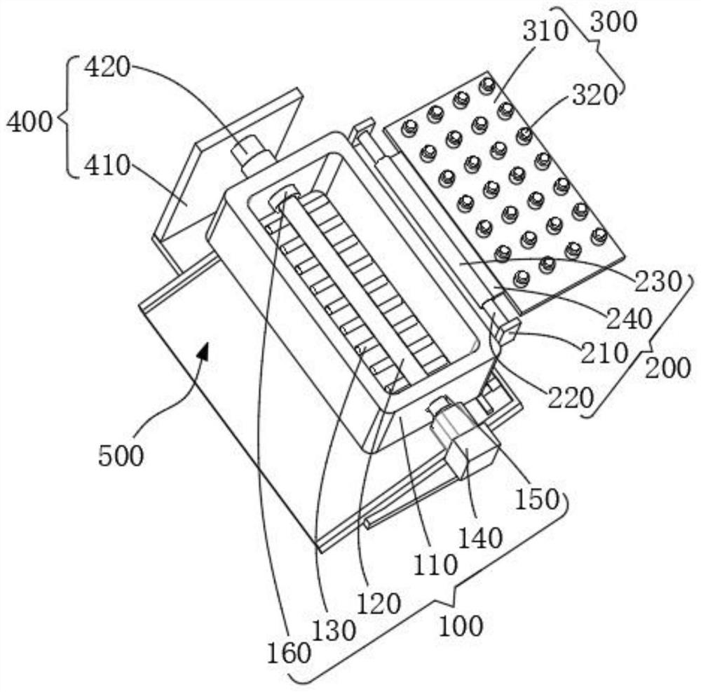
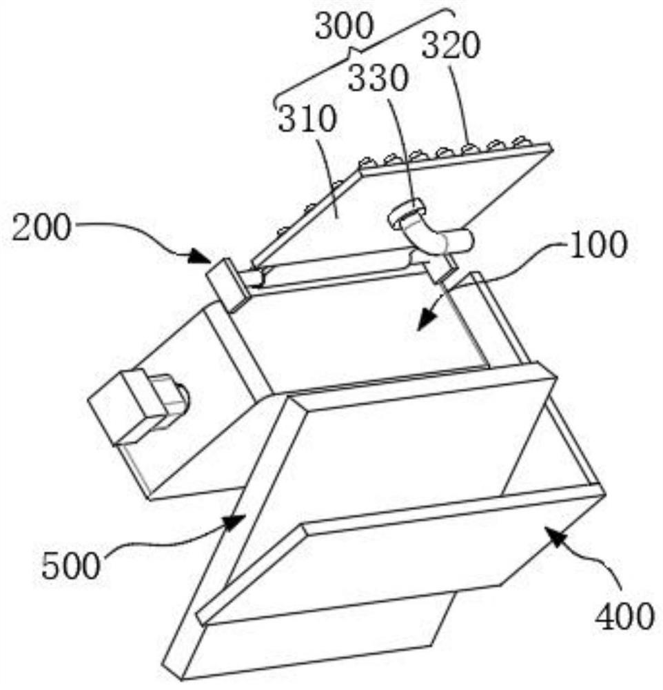
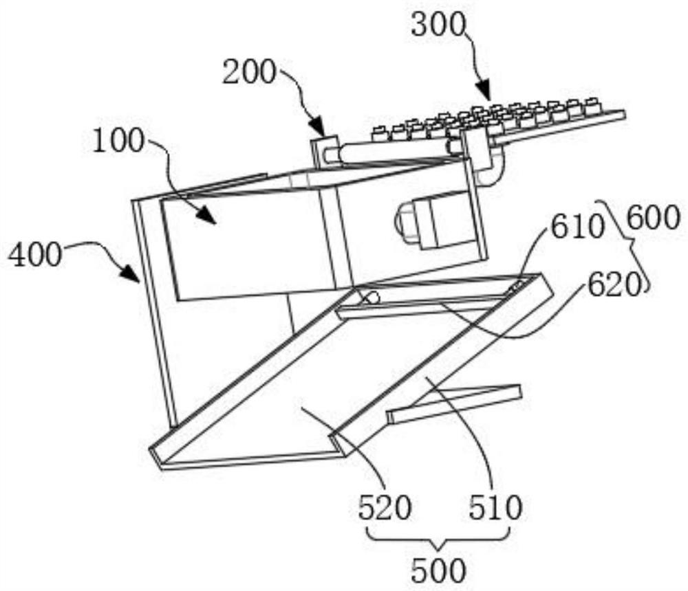
The invention discloses efficient sludge conditioning equipment which comprises a sludge conditioning and stirring assembly, a rotary connecting assembly and a conditioner feeding assembly. The sludge conditioning and stirring assembly comprises a conditioning storage frame, a rotating rod mounted in the conditioning storage frame, stirring cross rods fixed to the side faces of the periphery of the rotating rod, mounting holes formed in the side walls of the conditioning storage frame, a driving motor passing through the mounting hole and connected with the stirring cross rods, and a fixed sleeve fixed on the inner side wall of the conditioning storage frame and connected with the stirring cross rods in a sleeving manner. Traditional efficient sludge conditioning equipment is optimized. Through mutual cooperation of the rotary connecting structure and the conditioner feeding structure, the effect that sludge is fully covered by a fed conditioner is achieved, the fed conditioner fully covers the sludge while stirring is conducted, the conditioner makes contact with the sludge more uniformly, the stirring time is shortened, and the sludge conditioning efficiency is improved.

Description

technical field [0001] The invention relates to the technical field of sludge conditioning, in particular to high-efficiency sludge conditioning equipment. Background technique [0002] Sludge is deposited in still water or slow flowing water environment, formed by physical, chemical and biochemical actions, unconsolidated soft fine-grained or very fine-grained soil, which belongs to modern recent sediments. When modern factories are performing production work, Sludge accumulation will also occur. In order to avoid environmental pollution and form a better living environment, sludge dehydration treatment is generally required in current technologies. In order to improve the dehydration rate, conditioners will be added in the prior art to improve pollution. The dehydration rate of mud treatment. In the process of adding conditioner, in order to improve the mixing rate of the agent in the prior art, the conditioner is directly put into the conditioning frame and the sludge is ...

Claims


Application Information

Patent Timeline
IPC IPC(8): C02F11/14B01F7/04B01F15/02
CPCC02F11/14
Inventor 李林李刚洪根惠王成许晗田群超金圣
Owner 杭州国泰环保科技股份有限公司
Learn More