Isolation device for security and protection site

An isolation device and on-site technology, which is applied in the direction of fences, building types, buildings, etc., can solve the problems of inconvenient portability of isolation devices, and achieve the effects of improving portability and adjustability, improving portability, and improving space utilization

Inactive Publication Date: 2021-09-07
东莞市盈通环保科技有限公司
View PDF0 Cites 1 Cited by
  • Summary
  • Abstract
  • Description
  • Claims
  • Application Information

AI Technical Summary

Problems solved by technology

[0004] Aiming at the deficiencies of the prior art, the present invention provides an isolation device for security sites, which has the advantages of being easy to fold and carry, and solves the problem that the isolation device is not easy to carry

Method used


Image

  • Isolation device for security and protection site
  • Isolation device for security and protection site
  • Isolation device for security and protection site

Examples


Embodiment 1

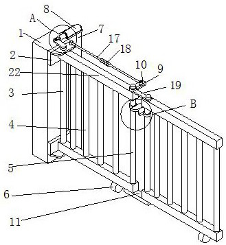
[0030] see figure 1 , the present invention provides a technical solution: an isolation device for security sites, including a fixed plate 1, the right surface of the fixed plate 1 is fixedly connected with two connecting parts 2, and the two connecting parts 2 are arranged in a vertical manner Fixedly connected to the right surface of the fixed plate 1, the shape of the two connecting pieces 2 are both "L" type, the right side of the fixed plate 1 is provided with an isolation device, the isolation device includes two limit rods 22, two limit rods 22 are respectively rotatably connected to the opposite surfaces of the two connectors 2, and the opposite surfaces of the two limit rods 22 are provided with transmission rods 3, the lower ends of the transmission rods 3 are rotationally connected with the lower connectors 2, and the lower ends of the transmission rods 3 The upper end of the transmission rod 3 passes through the upper connecting piece 2 and is rotationally connecte...

Embodiment 2

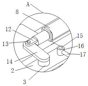
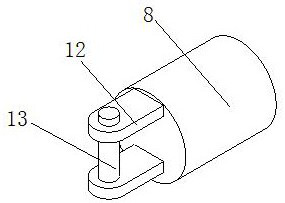
[0032] see Figure 2-Figure 3 , on the basis of Embodiment 1, the rear side of the fixed plate 1 is fixedly connected with a baffle 7, and the top of the baffle 7 is provided with a driving device, the driving device includes an electric control push rod 8, and the electric control push rod 8 is an existing structure , without further description here, the telescopic end of the electric control push rod 8 extends to the top of the fixed plate 1, and the telescopic end of the electric control push rod 8 is fixedly connected with two splints 12, and the two splints 12 are arranged up and down. Fixedly connected to the front side of the telescopic end of the electric control push rod 8, a connecting shaft 13 is fixedly connected to the opposite surfaces of the two splints 12, and a transmission shaft 14 is rotatably sleeved on the connecting shaft 13, and the right end of the transmission shaft 14 is connected to the transmission rod 3. The upper end is fixedly connected. When us...

Embodiment 3

[0034] see figure 1 , figure 2 with Figure 4 , on the basis of Embodiment 1, a linkage device is provided on the right side of the fixed plate 1, and the linkage device includes two fixed rods 9, and the two fixed rods 9 are respectively fixedly connected to the tops of the two upper limit rods 22, and the two The upper ends of the connecting rods 5 pass through two stop rods 22 and are fixedly connected with the two fixed rods 9, the opposite surfaces of the two fixed rods 9 are fixedly connected with the second guide rod 19, and the rear surface of the left fixed rod 9 is fixedly connected There is a first guide rod 10, and the shape of the linkage device is "L". Through the setting of the linkage device, the two isolation devices are connected together. The bottom of the two lower limit rods 22 is provided with a connecting plate 11, and the two connecting The lower end of the rod 5 runs through the limit rod 22 and is connected to the connecting plate 11 in rotation, t...


PUM


Abstract

The invention relates to the technical field of security devices, and discloses an isolation device for a security and protection site. The isolation device for the security and protection site comprises a fixed plate, wherein the right surface of the fixed plate is fixedly connected with two connecting pieces, the two connecting pieces are fixedly connected to the right surface of the fixed plate in an up-and-down arrangement mode, and the right side of the fixed plate is provided with isolation device bodies; a baffle is fixedly connected to the rear side of the fixed plate, and a driving device is arranged at the top of the baffle. When the whole isolation device for the security and protection site is withdrawn, the right isolation device body rotates while swinging along with the left isolation device body, and the left isolation device body is overlapped on the front surface of the right isolation device body after the two isolation device bodies swing backwards by 90 degrees from an unfolded state, so that the occupied area of the device is reduced when the device is withdrawn, more space is saved when the device is carried, the space utilization rate of the device is increased, and the device is convenient to carry.

Description

technical field [0001] The invention relates to the technical field of security devices, in particular to an isolation device for security sites. Background technique [0002] Security, that is, safety protection, the so-called safety, means no danger, no infringement, and no accidents; the so-called prevention means precautions, and precautions refer to being prepared to deal with attacks or avoid being victimized, and precautions refer to prevention and protection. A security device is a device or device that can provide prevention or protection to deal with attacks or avoid victims, so that the protected object is in a safe state where there is no danger, no infringement, and no accidents, so that the means of prevention can achieve or achieve the purpose of safety. . In order to prevent passers-by from entering the security site by mistake, most security sites will use isolation devices. Since most of the isolation devices on the security site are temporarily erected, m...

Claims


Application Information

Patent Timeline
Patent Type & Authority Applications(China)
IPC IPC(8): E04H17/14E04H17/20
CPCE04H17/14E04H17/1417E04H17/20
Inventor 詹翠红
Owner 东莞市盈通环保科技有限公司
Why Eureka
Try Eureka