
Interwell agitation type gas lift induced flow device and gas lift induced flow method

A technology of blowout induction and gas lift, which is applied to wellbore/well valve devices, earthwork drilling and production, wellbore/well components, etc. It can solve problems such as liquid accumulation and stop blowout in self-flowing wells, and achieve short operation period and high operation efficiency. The effect of low cost and convenient operation

Active Publication Date: 2021-09-07
CHINA NAT OFFSHORE OIL CORP +1
View PDF7 Cites 1 Cited by
  • Summary
  • Abstract
  • Description
  • Claims
  • Application Information

AI Technical Summary

Problems solved by technology

[0004] The purpose of the present invention is to provide an inter-well oscillating gas-lift induced blowout device and a gas-lift induced blowout method to solve the technical problem of on-site self-flowing wells accumulating liquid and stopping blowout

Method used


Image

  • Interwell agitation type gas lift induced flow device and gas lift induced flow method
  • Interwell agitation type gas lift induced flow device and gas lift induced flow method

Examples


Embodiment Construction

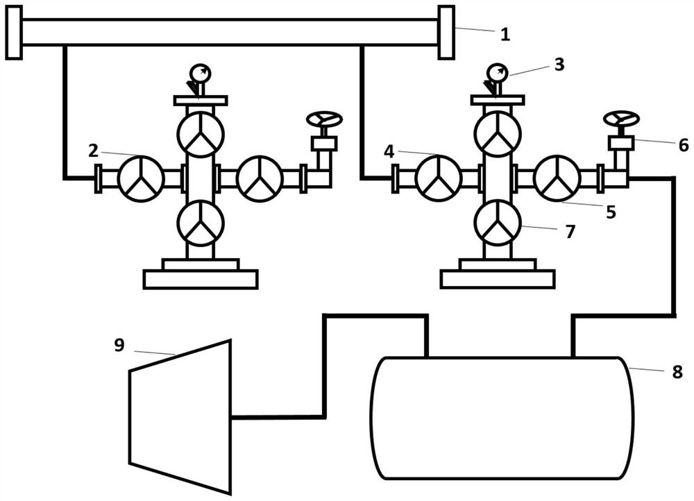
[0031] In order to better understand the purpose, structure and function of the present invention, an interwell agitation type gas lift induced blowout device and a gas lift induced blowout method of the present invention will be further described in detail below in conjunction with the accompanying drawings.

[0032] Such as Figure 1-Figure 2 As shown, the present invention includes: a kill manifold 1 arranged outside the wellbore, and a number control device connected to the kill manifold 1 (the number in this embodiment is two); wherein, the number control device in the number control device The first road: it is provided with: several well-side service oil pipe control valves 2 installed on the pipeline, the pipeline is cross-shaped, and each cross-shaped pipe has a well-side service oil pipe control valve 2; The well-side service oil pipe control valve 2 is also connected to the oil pressure gauge of the fault well through the pipeline; the well-side service oil pipe con...


PUM


Abstract

The invention discloses an interwell agitation type gas lift induced flow device and gas lift induced flow method. Small-period high-frequency open flow-well shut-in is achieved, elevation mixed liquid is gradually formed, the liquid column pressure drop in a shaft is reduced, the production pressure difference is increased, stratum oil gas is started to enter the shaft, and oil well self-flow is recovered; the method comprises the following steps that 1, a production wing valve and an oil nozzle of a fault well are closed, a production main valve and a wing valve of the fault well are opened, and high-pressure gas of an adjacent well enters an oil pipe of the fault well; 2, the well is soaked; 3, the wing valve of an adjacent well is closed, the wing valve and the oil nozzle of the fault well are opened, and gas and liquid in a shaft of the fault well are enabled to move upwards; 4, the oil nozzle of the fault well is closed, the migration of the gas at the upper part is stopped, and the upward migration speed of the far-end gas is slowed; the liquid at the lower part moves upwards and intrudes into the gas at the upper part to form a gas-liquid mixed flow state; 5, the process to enlarge the gas-liquid mixed flow-state liquid column is repeated, and the gas-liquid mixed flow-state liquid column is transported to the ground; and 6, formation oil gas is started to enter a shaft for induced injection and self-injection recovery. According to the interwell agitation type gas lift induced flow device and gas lift induced flow method, the operation cost is low; and the method is suitable for similar wells.

Description

technical field [0001] The invention belongs to the technical field of oil and gas exploitation, and in particular relates to an interwell oscillating gas lift induced blowout device and a gas lift induced blowout method. Background technique [0002] At present, in the production process of gushing wells in offshore oilfields, the energy of the formation is used to continuously lift the formation fluid to the ground to realize gushing production. However, during the production process of the self-flowing well, the problem of stopping the flow of the self-flowing well may be encountered due to insufficient formation productivity or bottom-hole fluid accumulation after the test operation is shut down. [0003] Existing common methods to solve the problem of fluid accumulation and stop flow in self-flowing wells: one is to inject oil pipes with high-pressure gas sources from adjacent wells to reduce the density of oil pipes, thereby reducing process back pressure for conventio...

Claims


Application Information

Patent Timeline
Patent Type & Authority Applications(China)
IPC IPC(8): E21B43/12E21B43/18E21B34/04E21B43/01
CPCE21B43/122E21B43/18E21B34/04E21B43/01
Inventor 袁勋李立民刘洋郭秩瑛
Owner CHINA NAT OFFSHORE OIL CORP
Learn More