
Electrical engineering and automation teaching device

A teaching device and electrical engineering technology, applied to electrical components, electrical operating teaching aids, televisions, etc., can solve problems that affect students' learning outcomes, make it difficult for students to display multiple electrical automation appliances, and lengthen teaching time.

Pending Publication Date: 2021-09-07
曹乒羽
View PDF3 Cites 0 Cited by
  • Summary
  • Abstract
  • Description
  • Claims
  • Application Information

AI Technical Summary

Problems solved by technology

Although this device has many beneficial effects, there are still the following problems: in the teaching work of electrical automation specialty, teachers often need to show students a variety of automation appliances, parts, etc. in the course of teaching. In other existing patented technologies such as Although CN207924977U can rotate and automatically display electrical components, the importance of electronic components is different, and the teaching focuses on it, so it is impossible to target the midpoint components, and the teaching focus is not prominent and it is easy to prolong the teaching time
Due to the large number of automation appliances, it is difficult for these two devices to show students multiple electrical automation appliances at the same time
This will cause teachers to spend too much time in the presentation process, which will reduce the teaching effect and affect the learning outcomes of students

Method used

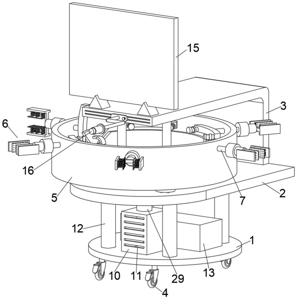
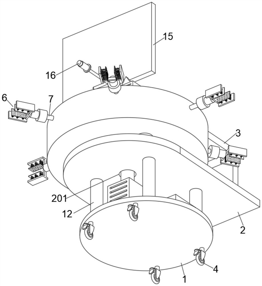
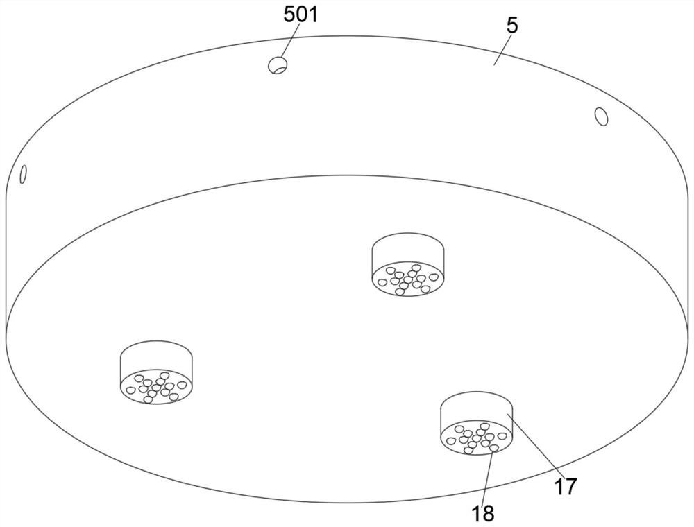

Image

  • Electrical engineering and automation teaching device
  • Electrical engineering and automation teaching device
  • Electrical engineering and automation teaching device

Examples


Embodiment Construction

[0029] In describing the present invention, it should be understood that the terms "center", "longitudinal", "transverse", "length", "width", "thickness", "upper", "lower", "front", " Orientation indicated by rear, left, right, vertical, horizontal, top, bottom, inside, outside, clockwise, counterclockwise, etc. The positional relationship is based on the orientation or positional relationship shown in the drawings, and is only for the convenience of describing the present invention and simplifying the description, rather than indicating or implying that the referred device or element must have a specific orientation, be constructed and operated in a specific orientation, Therefore, it should not be construed as limiting the invention.

[0030]In the description of the present invention, "plurality" means two or more, unless otherwise specifically defined.

[0031] see Figure 1-8 , the present invention provides a technical solution:

[0032] An electrical engineering and ...


PUM


Abstract

The invention discloses an electrical engineering and automation teaching device, and belongs to the technical field of electrical automation teaching equipment. The electrical engineering and automation teaching device comprises a fixed chassis, wherein a supporting plate is arranged on the top surface of the fixed chassis, a large-size liquid crystal display screen is arranged on the top surface of an L-shaped mounting plate, a high-definition camera is arranged on the front side of the L-shaped mounting plate, a motor is arranged in a motor box, a rotating sleeve is arranged in the middle of the top surface of the supporting plate, a plurality of mounting holes formed in the upper side of the outer wall of the circumference of the rotating sleeve, the circumferential inner wall of the mounting hole is rotatably connected with a movable rod, and a placing assembly is arranged outside the outer end face of the movable rod. Through cooperation of the motor arranged in the motor box, the rotating sleeve above the middle of the top surface of the supporting plate, the silica gel soft plate on the inner side of the inner end surface of the fixing plate and the first spring on the outer end surface of the silica gel soft plate, various automatic components can be displayed to students in the teaching process of a teacher, so that the understanding difficulty of the students on automatic components is reduced, and the teaching efficiency is improved.

Description

technical field [0001] The invention relates to the technical field of electrical automation teaching equipment, and more specifically relates to an electrical engineering and automation teaching device. Background technique [0002] Electrical engineering and its automation is a new discipline in the field of electrical information. Because it is closely related to people's daily life and industrial production, it has developed very rapidly and is relatively mature now. Now electrical automation has become an important part of the high-tech industry, widely used in industry, agriculture, national defense and other fields, and is playing an increasingly important role in the national economy. In the teaching process of electrical automation, teachers often use electrical engineering and automation teaching devices. The patent document of prior art publication number CN209401202U provides a kind of electrical engineering and automation teaching device, the device can make t...

Claims


Application Information

Patent Timeline
Patent Type & Authority Applications(China)
IPC IPC(8): G09B5/02G09B19/00H04N5/232
CPCG09B5/02G09B19/00H04N23/695
Inventor 曹乒羽
Owner 曹乒羽
Learn More