
Antenna device of MPCVD equipment

An antenna device and antenna technology, applied in the direction of antenna support/installation device, antenna, antenna parts, etc., can solve the problems of unsatisfactory plasma flame shape, poor controllability of plasma flame, large microwave conduction loss, etc., and achieve cooling effect Better, better symmetry, and less microwave conduction loss

Pending Publication Date: 2021-09-07
碳方程新材料(山西)有限公司
View PDF0 Cites 0 Cited by
  • Summary
  • Abstract
  • Description
  • Claims
  • Application Information

AI Technical Summary

Problems solved by technology

[0006] The object of the present invention is to provide a kind of MPCVD equipment antenna device, to solve the problem that the microwave generated by the existing microwave power supply in the above background technology is introduced into the cavity, the loss of the microwave conduction process is relatively large, the shape of the obtained plasma flame is not ideal, and the controllability of the plasma flame is poor. , and the cooling effect is poor, resulting in a limited service life

Method used


Image

  • Antenna device of MPCVD equipment
  • Antenna device of MPCVD equipment
  • Antenna device of MPCVD equipment

Examples


Embodiment Construction

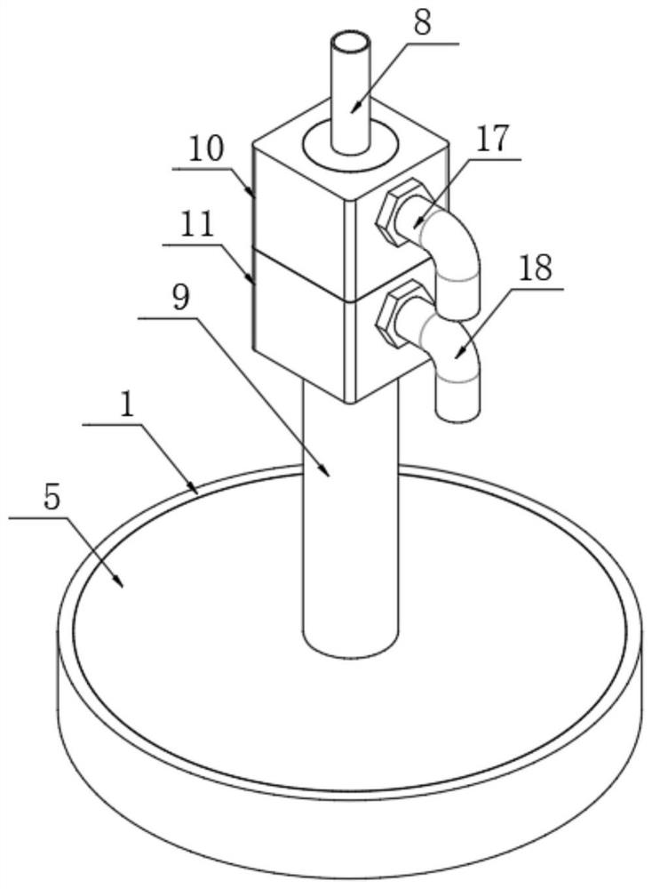
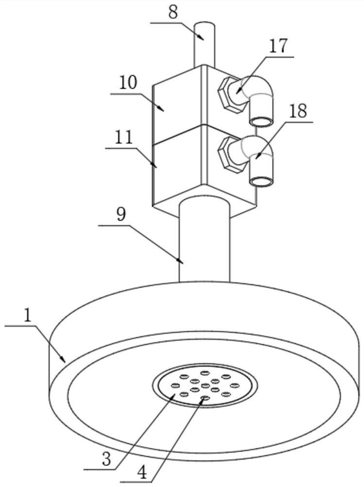
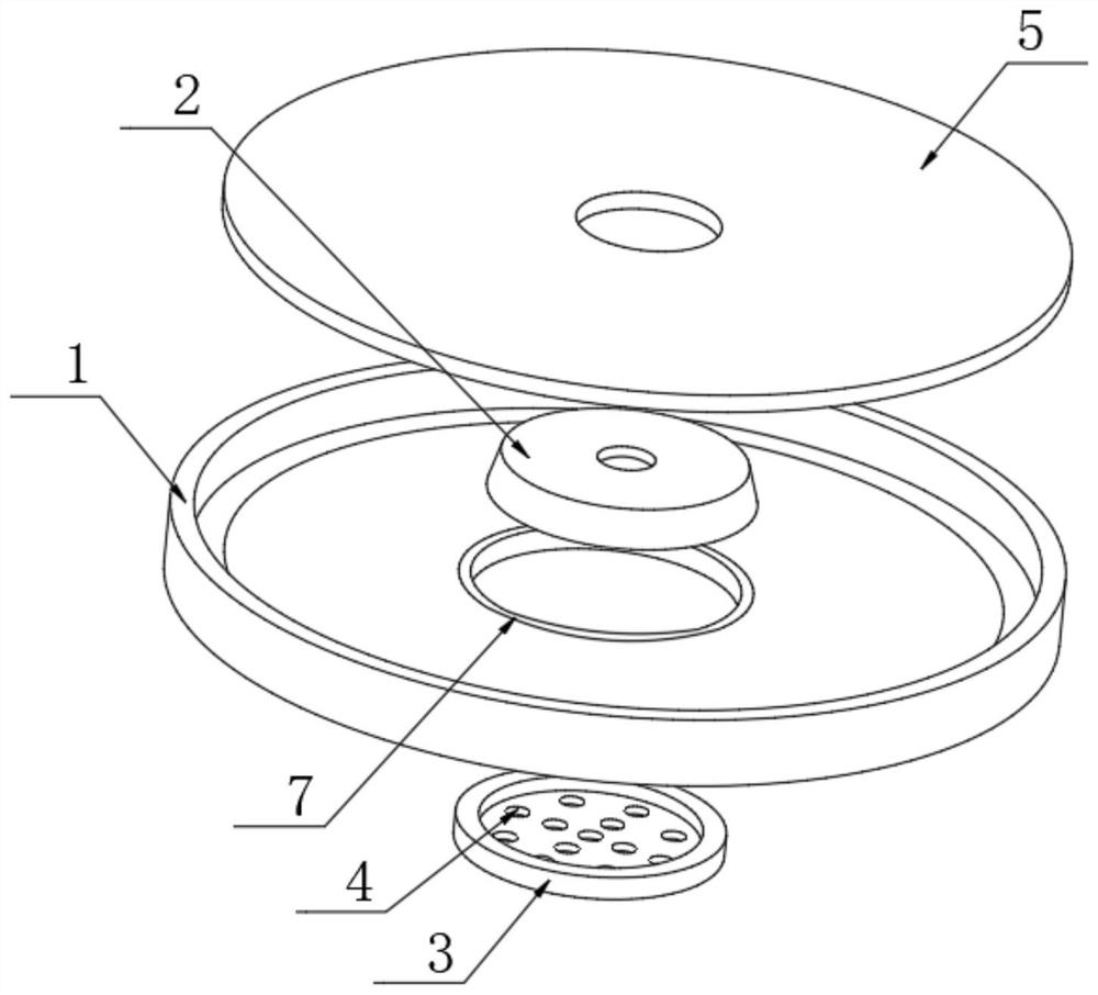
[0037] like Figure 1-6 As shown, an antenna includes an antenna body 1, the antenna body 1 is set in an inverted cone shape, and the bottom end of the antenna body 1 is provided with an upwardly turned cavity, so that both sides of the antenna body 1 form slopes, in actual use During the process, when water flows into the inside of the antenna body 1, it can better contact it, and prolong the contact time to achieve a better cooling effect. The bottom end of the antenna body 1 is provided with a boss 2, and the antenna body 1 The bottom is provided with a through groove 7, and the through groove 7 is provided with an air intake plate 3, and the air intake plate 3 is provided with a penetrating exhaust hole 4, and the air intake plate 3 is threadedly connected with the antenna body 1, and the antenna An opening is provided on the top of the main body 1, and a cover plate 5 is provided at the opening, and a closed accommodation cavity 6 is formed between the cover plate 5 and t...


PUM


Abstract

The invention discloses an antenna device of MPCVD (Mobile Plasma Chemical Vapor Deposition) equipment. The antenna device comprises an antenna body; a cover plate is arranged on the top of the antenna body; a closed accommodating cavity is formed between the cover plate and the antenna body; a water inlet channel is arranged at the top of the antenna body along the axis; and an independent water outlet channel is arranged on the outer side of the water inlet channel. Water is injected into the inner wall of the antenna body through the water inlet channel to cool the antenna body and is discharged through the water outlet channel to cool the antenna body. Water in the sealed cavity can flow upwards through the water outlet channel between a middle wall pipe and an outer wall pipe and is discharged outwards through a water outlet clamping sleeve connector on a water outlet block, and the antenna body can be fully cooled. As the antenna body is arranged to be in an inverted cone shape, in actual use, the microwave feedback is low, the microwave conduction loss is small, and the obtained plasma flame is high in energy density, good in symmetry, uniform in temperature distribution and good in controllability.

Description

Technical field [0001] The present invention relates to the field of MPCVD technology, and in particular to an antenna device for MPCVD equipment. Background technique [0002] The antenna used in MPVCD equipment is the core component. Different manufacturers have different designs, depending on the design of the microwave power supply and cavity. Different antennas have different effects on the plasma flame. The purpose is to obtain the lowest microwave feedback, reduce microwave loss, and obtain a controllable plasma flame. [0003] However, when the current MPVCD equipment is in use, the microwave generated by the microwave power supply is introduced into the cavity, and the loss in the microwave conduction process is large. The shape of the plasma flame obtained is not ideal, the controllability of the plasma flame is poor, and the cooling effect is poor, resulting in its service life being limited. limit. [0004] Therefore, it is necessary to provide an antenna devic...

Claims


Application Information

Patent Timeline
IPC IPC(8): H01Q1/00H01Q1/12H01Q1/42
CPCH01Q1/02H01Q1/12H01Q1/42
Inventor 赵俊芳郭志刚刘永宁
Owner 碳方程新材料(山西)有限公司
Learn More