
Flame retardant power cable protection tube

A power cable and protection tube technology, applied in the field of flame retardant power cable protection tube, can solve the problems of low power cable protection strength, poor power cable stability, poor flame retardant performance, etc., to achieve enhanced protection effect, enhanced Stability, improve the effect of pressing

Active Publication Date: 2022-05-17
江苏衡羽电力有限公司
View PDF6 Cites 0 Cited by
  • Summary
  • Abstract
  • Description
  • Claims
  • Application Information

AI Technical Summary

Problems solved by technology

[0003] The purpose of the present invention is to solve the problems of poor flame retardancy, poor stability of the power cable in the protection tube, low versatility, and low protection strength of the power cable existing in the existing power cable protection tube, and to provide a reasonable structural design, Good flame retardant performance, good stability of the power cable in the protection tube, high versatility, good power cable protection effect, flame retardant power cable protection tube

Method used


Image

  • Flame retardant power cable protection tube
  • Flame retardant power cable protection tube
  • Flame retardant power cable protection tube

Examples


Embodiment 1

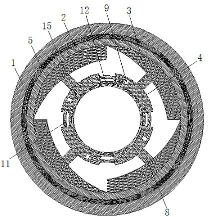
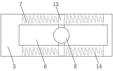
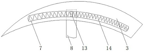
[0024] If attached Figure 1-7 As shown: a flame retardant power cable protection tube, including an external pipe body 1, an inner pipe body 2, a positioning block 3 and a fastening block 4, characterized in that: the inner pipe body 2 is placed in the outer pipe body 1, the inner pipe body 2 and the outer pipe body 1 are connected by thread, to facilitate the installation between the outer pipe body 1 and the inner pipe body 2, improve the assembly efficiency of the power cable protection tube, the positioning block 3 is provided in the inner pipe body 2, the positioning block 3 is provided with a positioning groove 6, and the limited position groove 7 is set on the positioning block 3, And the limit groove 7 and the positioning groove 6 is connected, the middle of the fastening block 4 is provided with a connecting rod 8, at one end of the fastening block 4 is provided with a card slot 9, a fixing slot 10, at the other end of the fastening block 4 is provided with a card post 11...

Embodiment 2

[0032] If attached Figure 8 As shown: a flame retardant power cable protection tube, including an external pipe body 1, an inner pipe body 2, a positioning block 3 and a fastening block 4, characterized in that: the inner pipe body 2 is placed in the outer pipe body 1, the inner pipe body 2 and the outer pipe body 1 are connected by thread, to facilitate the installation between the outer pipe body 1 and the inner pipe body 2, improve the assembly efficiency of the power cable protection tube, the positioning block 3 is provided in the inner pipe body 2, the positioning block 3 is provided with a positioning groove 6, and the limited position groove 7 is set on the positioning block 3, And the limit groove 7 and the positioning groove 6 is connected, the middle of the fastening block 4 is provided with a connecting rod 8, at one end of the fastening block 4 is provided with a card slot 9, a fixing slot 10, at the other end of the fastening block 4 is provided with a card post 11, ...


PUM


Abstract

The invention provides a flame-retardant power cable protection tube, which includes an outer tube body, an inner tube body, a positioning block and a fastening block, and is characterized in that: the inner tube body is placed in the outer tube body, and the positioning block is set In the inner tube body, a positioning groove is arranged on the positioning block, and a limiting groove is arranged on the positioning block, and the limiting groove is connected with the positioning groove. There are card slots and fixing slots, and a card column and a fixing block are provided at the other end of the fastening block, connecting two adjacent fastening blocks through the card posts and card slots, and extending the top of the connecting column into the positioning groove . In the present invention, a flame-retardant pad is provided on the bottom surface of the fastening block and the fixed block, and the flame-retardant pad is made of flame-retardant epoxy resin material, and the flame-retardant pad can be used to flame-retardant the surface of the cable to improve the safety of the cable protection tube. Flame retardant performance, thereby improving the quality performance of the cable protection tube.

Description

Technical field [0001] The present invention relates to a cable protection tube, specifically to a flame retardant power cable protection tube. Background [0002] With the rapid development of power cable buried laying projects, the cable sleeve is suitable for telecommunications, power engineering, transportation, urban construction and other fields. For example, the patent number 201821982642.6 publishes a PVC power cable protection tube, which solves the problem of the cable being damaged when bending and losing the function of shielding external signals, but it has the problems of poor flame retardant performance, poor stability of the power cable in the protection tube, small versatility, and low power cable protection strength. Contents of the Invention [0003] Object of the present invention is to provide a reasonable structural design, good flame retardant performance, good flame retardant power cable protection tube, good stability of power cable protection effect, h...

Claims


Application Information

Patent Timeline
Patent Type & Authority Patents(China)
IPC IPC(8): H02G9/06H02G3/04
CPCH02G9/06H02G3/0412H02G3/0462Y02A30/14
Inventor 丁召亮
Owner 江苏衡羽电力有限公司
Learn More