Direct cooling system applied to rotor and winding of high-speed permanent magnet motor

A permanent magnet motor and cooling system technology, applied in the shape/style/structure of winding conductors, electric components, magnetic circuit rotating parts, etc., can solve the problems of high demand for pump capacity and high pressure of axial flow

Pending Publication Date: 2021-09-07
CHINA FIRST AUTOMOBILE
View PDF8 Cites 4 Cited by
  • Summary
  • Abstract
  • Description
  • Claims
  • Application Information

AI Technical Summary

Problems solved by technology

[0007] The inlet and outlet of the rotor oil circuit involved in this patent are arranged in the hollow shaft, one end flows in - axial flow cooling - the other end flows out, this process is all completed in the rotor assembly, and does not inv...

Method used


Image

  • Direct cooling system applied to rotor and winding of high-speed permanent magnet motor
  • Direct cooling system applied to rotor and winding of high-speed permanent magnet motor
  • Direct cooling system applied to rotor and winding of high-speed permanent magnet motor

Examples


Embodiment Construction

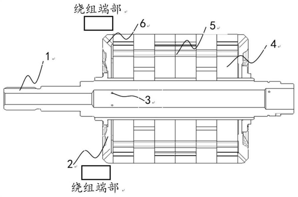
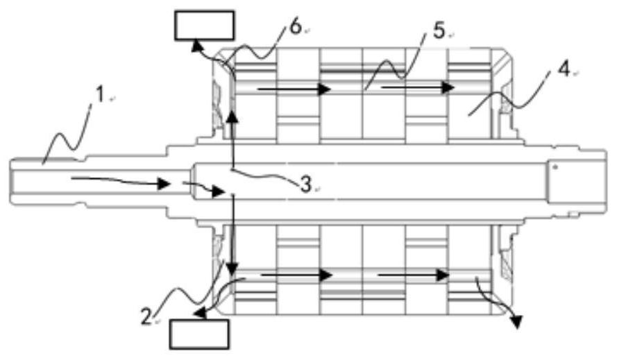
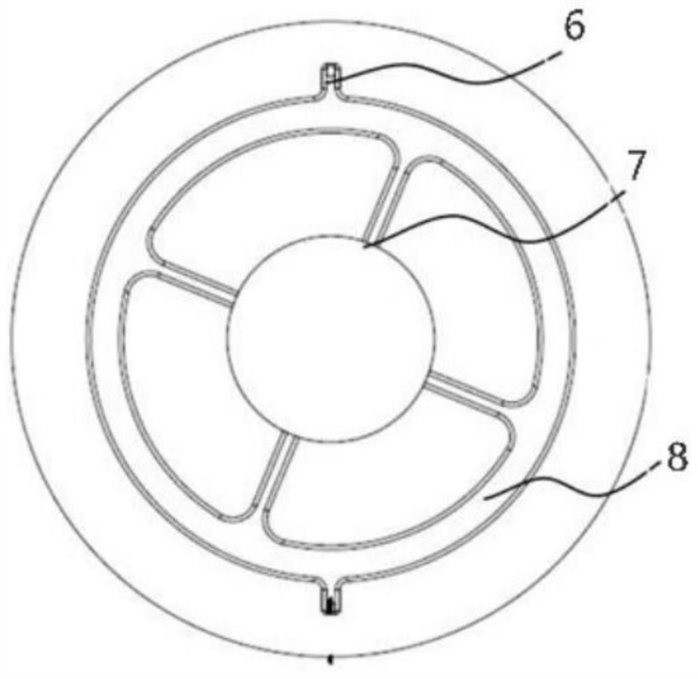
[0036] In order to make the objectives, technical solutions and advantages of the present invention clearer, the technical solutions in the embodiments of the present invention will be described in more detail below in conjunction with the drawings in the embodiments of the present invention. In the drawings, the same or similar reference numerals denote the same or similar elements or elements having the same or similar functions throughout. The described embodiments are some, but not all, embodiments of the invention. The embodiments described below by referring to the figures are exemplary and are intended to explain the present invention and should not be construed as limiting the present invention. Based on the embodiments of the present invention, all other embodiments obtained by persons of ordinary skill in the art without creative efforts fall within the protection scope of the present invention. Embodiments of the present invention will be described in detail below ...


PUM

PropertyMeasurementUnit
Depthaaaaaaaaaa

Abstract

The invention relates to a direct cooling system applied to a rotor and a winding of a high-speed permanent magnet motor. Cooling liquid enters from a hollow cavity of a rotating shaft, passes through a rotating shaft guide hole under the rotating centrifugal effect of the rotor and flows into an area formed by the end face of the end plate and a rotor core; the area formed by the end face and the rotor core is communicated with a rotor de-weight hole and an end plate guide hole; one part of the cooling liquid is thrown out from the end plate guide hole and is in contact with the inner end face of the winding for heat exchange, and winding cooling is completed; and the other part of the cooling liquid passes through the rotor de-weight hole communicated with the rotor core, so that the cross flow in the axial direction is completed, and the rotor iron core is cooled. According to the invention, the hollow shaft, the end plates, the rotor core, the permanent magnet magnetic isolation bridges and other structures are fully utilized to set the cooling flow channels, so that the influence of the cooling flow channels on electromagnetic performance is reduced; through a rotor encapsulation process, the change of a cooling flow channel structure is realized, and the flow demand and the temperature rise demand are balanced. and the rotation inertia is reduced, the oil stirring loss is reduced, and the motor performance output and the system efficiency are improved.

Description

technical field [0001] The invention belongs to the technical field of new energy vehicle power assembly cooling, and relates to a direct cooling system applied to the rotor and winding of a high-speed permanent magnet motor. Background technique [0002] With the continuous increase in the speed demand of permanent magnet synchronous motors, the heat generated by the rotor and the magnetic steel at high speeds will increase, and the temperature will increase, which will cause the performance of the magnetic steel to decline, affect the performance output of the motor assembly, and even cause irreversible demagnetization; affect the power performance of pure electric vehicles, Reliability and even safety. The importance of rotor cooling is highlighted, and the design methods and cooling effects vary. [0003] At present, the oil-cooled shaft method is mostly used for rotor cooling, and the cooling oil is passed through the hollow shaft, and the cooling is completed through ...

Claims


Application Information

Patent Timeline
IPC IPC(8): H02K1/32H02K9/19H02K3/24H02K1/27
CPCH02K1/32H02K9/19H02K3/24H02K1/2706H02K2213/03Y02T10/64
Inventor 赵慧超于拓舟高一郭守仑张颖王金昊林展汐张莉魏颖颖肖庚
Owner CHINA FIRST AUTOMOBILE
Why Eureka
Try Eureka