
Remote control type sphygmomanometer with data transmission function and using method thereof

A data transmission and remote control technology, applied in the direction of cardiac catheterization, etc., can solve the problems of increasing the workload of the staff, the inability to save the measurement data of the sphygmomanometer in time, and the lack of automatic data output function, etc.

Pending Publication Date: 2021-09-10
JIANGSU YUANYAN MEDICAL EQUIP
View PDF3 Cites 0 Cited by
  • Summary
  • Abstract
  • Description
  • Claims
  • Application Information

AI Technical Summary

Problems solved by technology

[0003] 1. At present, electronic sphygmomanometers on the market are generally used in the way of connecting to electricity, which makes it impossible to carry and use electronic sphygmomanometers in places without electricity, which seriously affects the scope and applicability of electronic sphygmomanometers; 2. At present The measurement data of electronic sphygmomanometers on the market are generally recorded visually, which makes it very inconvenient to record data and is prone to errors. It does not have the functions of data storage and secondary display, so that the measurement data of sphygmomanometers cannot be saved in time. This is very inconvenient when it is necessary to measure the blood pressure of a large number of people at one time, which seriously increases the workload of the staff; 3. The sphygmomanometers currently on the market do not have a measurement prompt function, nor do they have an automatic data output function. The children of the elderly work away from home, which makes it difficult to obtain blood pressure monitoring data in time, and is also not conducive to monitoring the blood pressure of their parents. There are serious potential safety hazards; therefore, it is necessary to design a remote blood pressure monitor with data transmission Count and how to use it

Method used


Image

  • Remote control type sphygmomanometer with data transmission function and using method thereof
  • Remote control type sphygmomanometer with data transmission function and using method thereof
  • Remote control type sphygmomanometer with data transmission function and using method thereof

Examples


Embodiment Construction

[0032] In order to make the technical means, creative features, goals and effects achieved by the present invention easy to understand, the present invention will be further described below in conjunction with specific embodiments.

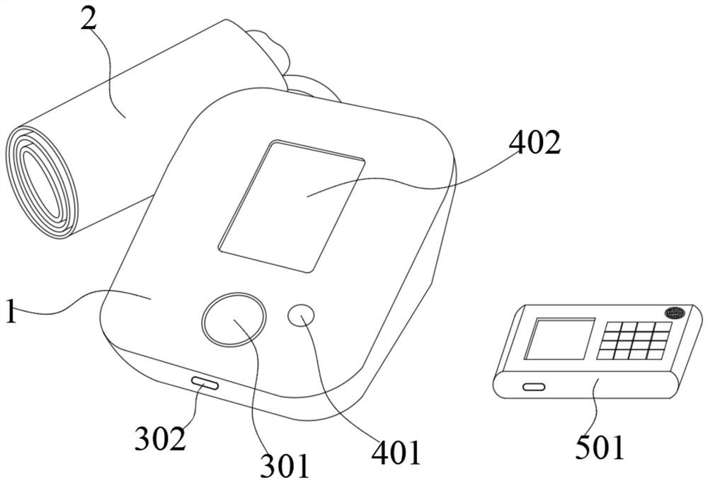
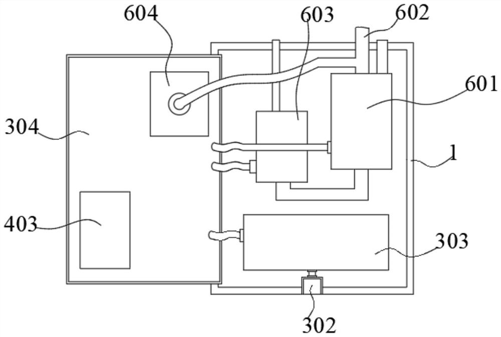
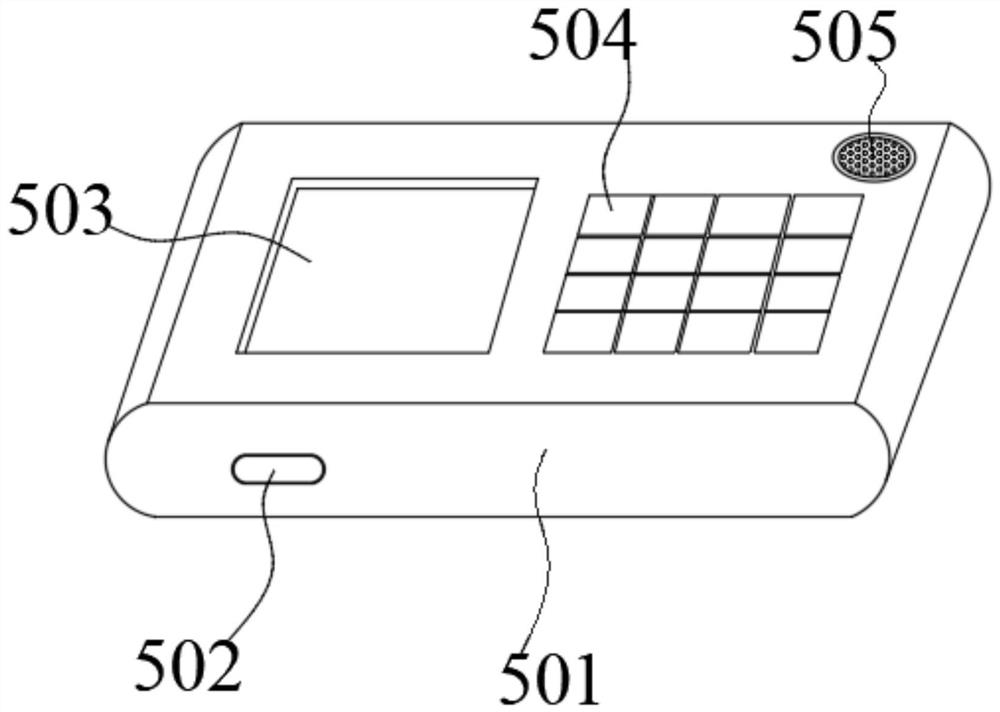
[0033] Such as Figure 1-4 As shown, a remote-controlled sphygmomanometer with data transmission function and its use method include a base 1, a control mechanism, a measurement mechanism, a display mechanism and a monitoring mechanism. The base 1 is internally provided with a control mechanism, and the control mechanism A measuring mechanism and a display mechanism are electrically connected, and the display mechanism is wirelessly connected with a monitoring mechanism;

[0034] The control mechanism includes a control switch 301, a charging interface A302, a battery A303, and a main control chip 304. The outer wall of the base 1 is plugged with a charging interface A302, and the signal output terminal of the charging interface A302 is connected ...


PUM


Abstract

The invention discloses a remote control type sphygmomanometer with a data transmission function and a using method thereof. The remote control type sphygmomanometer comprises a base, a control mechanism, a measuring mechanism, a display mechanism and a monitoring mechanism, the control mechanism is arranged in the base, the control mechanism is electrically connected with the measuring mechanism and the display mechanism, and the display mechanism is in wireless communication connection with the monitoring mechanism. The control mechanism comprises a control switch, a charging interface A, a storage battery A and a main control chip. Through the control mechanism and the measuring mechanism, the remote control type sphygmomanometer can be used in a rechargeable battery power supply mode and can be used in a portable mode without a power supply; through the display mechanism and the monitoring mechanism, measurement data can be displayed in real time, stored in real time and secondarily displayed; and through the monitoring mechanism, the remote control type sphygmomanometer has a measurement time prompting function and a remote data transmission function, and is suitable for being widely popularized and used.

Description

technical field [0001] The invention relates to the technical field of intelligent sphygmomanometers, in particular to a remote-controlled sphygmomanometer with a data transmission function and a usage method thereof. Background technique [0002] Electronic sphygmomanometer is a medical device that uses modern electronic technology and the principle of indirect blood pressure measurement to measure blood pressure; electronic sphygmomanometers are divided into arm type, wrist type, and watch type; its technology has experienced the most primitive first generation (mechanical constant speed Exhaust valve), the second generation (electronic servo valve), the third generation (pressurized synchronous measurement) and the fourth generation (integrated air circuit); usually composed of blocking cuffs, sensors, air pumps, and measurement circuits; An electronic device for blood pressure measurement using the oscillometric method, the Korotkonic method, or similar non-invasive bloo...

Claims


Application Information

Patent Timeline
IPC IPC(8): A61B5/0225
CPCA61B5/0225
Inventor 王东林吉连生
Owner JIANGSU YUANYAN MEDICAL EQUIP
Learn More