Axial drive mechanism, automatic injection device and method of using the same
An axial drive, automatic injection technology, applied in the direction of automatic injectors, syringes, hypodermic injection devices, etc., can solve the problems of inability to accurately identify the injection state, the product cannot be guaranteed to be self-locking, and violates human factors engineering, so as to achieve product compliance. Good sex, easy to sell and transport, reduce the effect of fear
- Summary
- Abstract
- Description
- Claims
- Application Information
AI Technical Summary
Problems solved by technology
Method used
Image

Examples
Embodiment 1
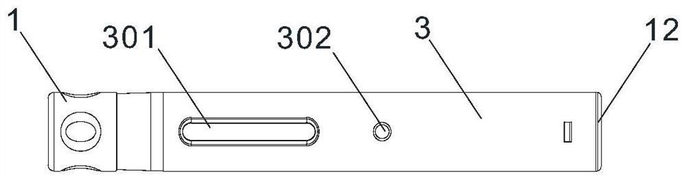
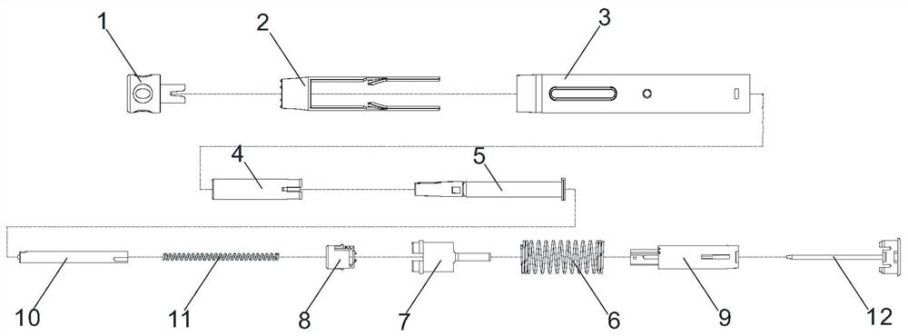
[0086] like Figures 1 to 6b , Figures 7a to 17 As shown, an automatic injection device with dual visual feedback includes a head end protective cap 1, a safety sleeve 2, an outer casing 3, a protective casing 4, a pre-filled syringe 5, a return spring 6, a release sleeve 7, a limit Sound ring 8, guide sleeve 9, push rod 10, injection spring 11 and bottom cover 12, injection spring 11 is provided between push rod 10 and bottom cover 12, head end protective cap 1, safety sleeve 2, shell 3 and protection The shell 4 constitutes a shell assembly, the return spring 6, the release sleeve 7, the limit sound ring 8, the guide sleeve 9, the push rod 10 and the bottom cover 12 constitute an axial drive mechanism with visual feedback. The front end of the push rod 10, That is, the end facing the prefilled syringe 5 is the output end of the axial drive mechanism, and the prefilled syringe 5 and the axial drive mechanism are arranged in the cavity of the housing assembly. Safety sleeve...
Embodiment 2
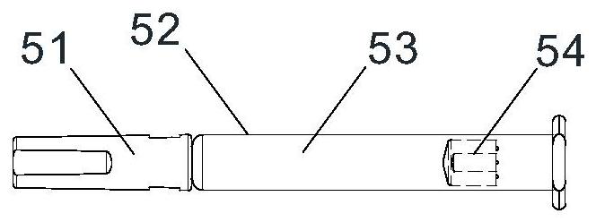
[0097] like Figure 6c As shown, the front end of the push rod 10 is equipped with a spacer 1004 that can rotate around the axis of the push rod 10. The spacer 1004 functions as a plane bearing. When the push rod 10 is advanced, the spacer 1004 contacts the piston 54, and the two keep the Relatively stationary, the push rod 10 and the piston 54 rotate relative to each other, which can reduce the resistance encountered during the rotation of the push rod. The rest are the same as in Example 1.
Embodiment 3
[0099] like Figures 18 to 20d As shown, the tile-shaped long cantilever is provided with a hollow area, the hollow area is provided with a safety sleeve self-locking cantilever 203, the safety sleeve self-locking cantilever 203 is provided with a self-locking bump 204, and the self-locking structure is provided with On the housing assembly, the self-locking structure includes a safety sleeve self-locking cantilever 203 arranged on the safety sleeve 2 and a lock block 304 arranged on the inner wall of the casing 3 , and the lock block 304 protrudes radially on the inner wall of the casing 3 . , the lock block 304 is V-shaped as a whole, and the lock block 304 is provided with an activation side wall 3041 and a reset side wall 3042 intersecting at the rear end of the lock block 304. The front end of the lock block 304 is provided with a V-shaped groove 3043 . The starting side wall 3041 and the inner wall of the housing 3 opposite to it constitute the starting movement track 3...
PUM
 Abstract
Description
Claims
Application Information
 - R&D
- Intellectual Property
- Life Sciences
- Materials
- Tech Scout
- Unparalleled Data Quality
- Higher Quality Content
- 60% Fewer Hallucinations
Browse by: Latest US Patents, China's latest patents, Technical Efficacy Thesaurus, Application Domain, Technology Topic, Popular Technical Reports.
© 2025 PatSnap. All rights reserved.Legal|Privacy policy|Modern Slavery Act Transparency Statement|Sitemap|About US| Contact US: help@patsnap.com