Clamping device

A clamping device and clamping piece technology, applied in metal processing equipment, welding equipment, manufacturing tools, etc., can solve the problems of complex structure, poor stability, poor self-locking effect, etc.

Active Publication Date: 2021-09-10
黄建财
View PDF7 Cites 1 Cited by
  • Summary
  • Abstract
  • Description
  • Claims
  • Application Information

AI Technical Summary

Problems solved by technology

[0006] First, as shown in the Chinese invention with the patent number 201710435364.6 and the patent name of the light pipe cutting chuck, it is driven by a connecting rod to drive the claws to approach or move away from the pipe, thereby realizing the clamping or loosening of the pipe. This method has a complex structure, poor clamping stability, poor self-locking effect, and

Method used


Image

  • Clamping device
  • Clamping device
  • Clamping device

Examples


Embodiment Construction

[0053] In order to facilitate the understanding of the present invention, the present invention will be described more fully below with reference to the associated drawings. Preferred embodiments of the invention are shown in the accompanying drawings. However, the present invention can be embodied in many different forms and is not limited to the embodiments described herein. On the contrary, the purpose of providing these embodiments is to make the disclosure of the present invention more thorough and comprehensive.

[0054] It should be noted that when an element is referred to as being “fixed” to another element, it can be directly on the other element or there can also be an intervening element. When an element is referred to as being "connected to" another element, it can be directly connected to the other element or intervening elements may also be present. The terms "vertical," "horizontal," "left," "right," and similar expressions are used herein for purposes of ill...


PUM


Abstract

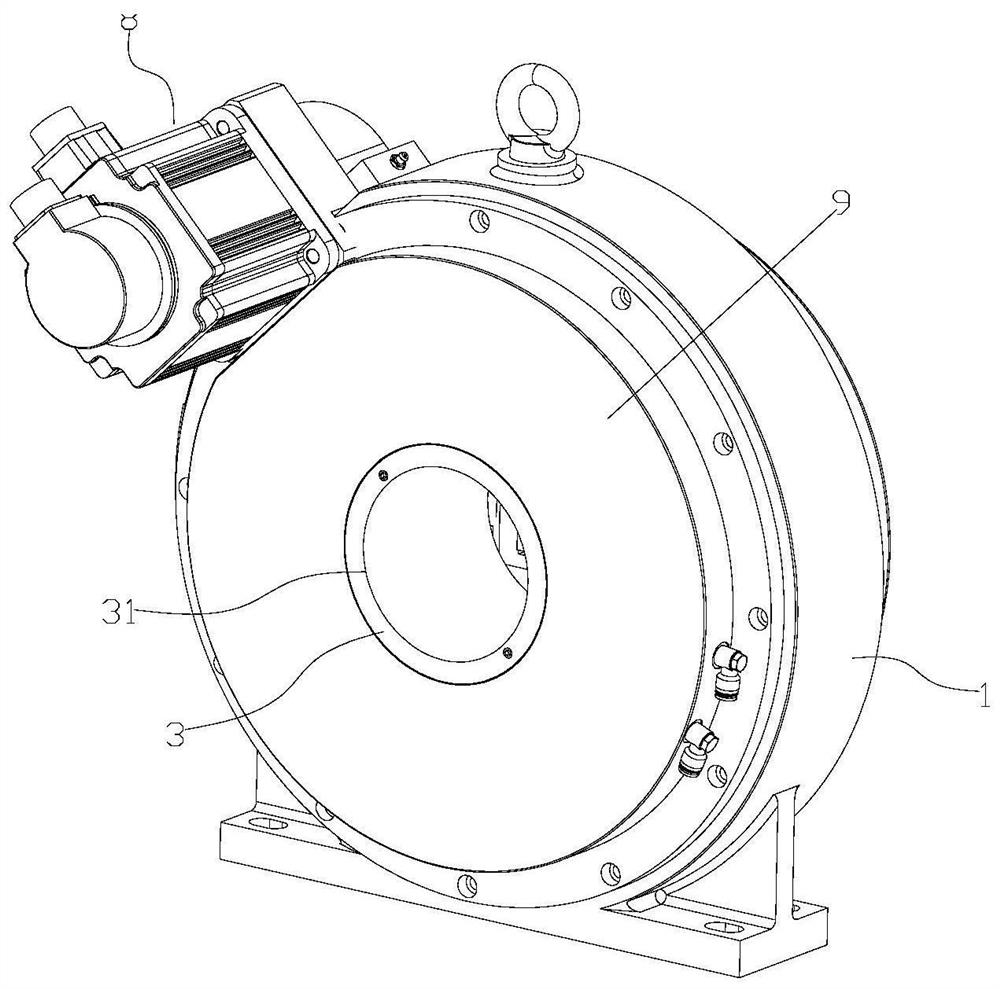
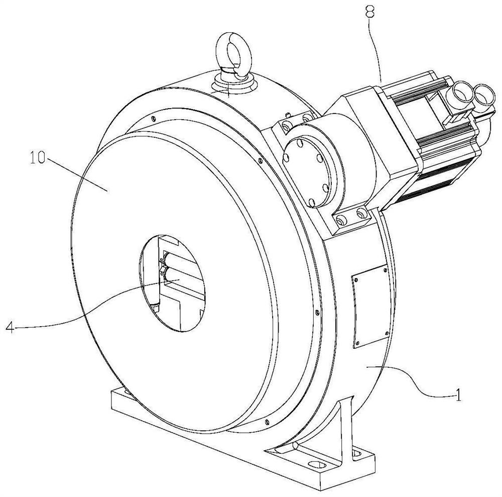
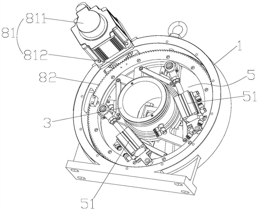
The invention relates to a clamping device which at least comprises a shell, a rotating disc, a shaft sleeve, a clamping mechanism and a first driving mechanism, wherein the clamping mechanism at least comprises a set of clamping assemblies, and the clamping assemblies are installed on the rotating disc in a sliding mode and matched with a to-be-clamped piece; the first driving mechanism is matched with the clamping mechanism; the first driving mechanism at least comprises a first driving assembly; each first driving assembly comprises a first driving part, a rotating plate, push rods and movable blocks, the rotating plate sleeves the periphery of the shaft sleeve and can rotate relative to the shaft sleeve, the push rods are mounted on the rotating plate, the movable blocks are movably mounted on the rotating disc, one end of each movable block movably sleeves the corresponding push rod, and the other ends of the movable blocks sequentially penetrate through the rotating plate and the rotating disc to be connected with the corresponding clamping assembly; and the first driving parts can drive the rotating plates to rotate, the rotating plates rotate to drive the push rods to push the movable blocks, and the movable blocks push the clamping assemblies to slide. The clamping device is simple in overall structure, low in cost, good in stability, high in self-locking function and convenient to maintain and use.

Description

technical field [0001] The invention relates to the field of laser tube cutting, in particular to a clamping device. Background technique [0002] The laser cutting device uses a high-power-density laser beam to irradiate the material to be cut, so that the material is heated to the gasification temperature and evaporates to form a cavity. As the beam moves to the material, the hole continuously forms a narrow slit to complete the cutting of the material. cutting. [0003] When laser cutting pipes are used, usually the laser head does not move relative to the axial direction of the pipe, and the pipe needs to be clamped by a clamping device such as a chuck, and at the same time realize the axial movement relative to the laser head and the rotation of the relative laser head, so as to realize continuous processing and feeding the goal of. [0004] The existing chuck clamping device generally includes a shaft sleeve for the piece to be clamped to pass through, a clamping mec...

Claims


Application Information

Patent Timeline
IPC IPC(8): B23K26/38B23K26/70
CPCB23K26/38B23K26/70B23K26/702Y02P70/50
Inventor 黄建财
Owner 黄建财
Why Eureka
Try Eureka