Device for grinding groove of aluminum alloy profile

A technology of aluminum alloy profiles and notches, which is applied in the direction of grinding drive devices, grinding machines, grinding racks, etc., and can solve the problems of low efficiency of aluminum alloy profile grooves, etc.

Pending Publication Date: 2021-09-10
湖南千源铝业有限公司
View PDF0 Cites 2 Cited by
  • Summary
  • Abstract
  • Description
  • Claims
  • Application Information

AI Technical Summary

Problems solved by technology

[0005] The purpose of the present invention is to provide a grinding device for aluminum alloy profile grooves in order

Method used


Image

  • Device for grinding groove of aluminum alloy profile
  • Device for grinding groove of aluminum alloy profile
  • Device for grinding groove of aluminum alloy profile

Examples


Embodiment 1

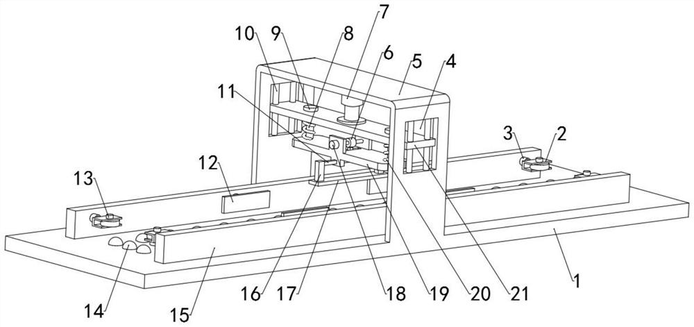
[0028] see Figure 1-3 , an aluminum alloy profile groove grinding device, including an operation panel 1, an inverted U-shaped support 5 is fixed on the top of the operation panel 1, and the inner cavity of the support 5 is provided with a hydraulic rod 7, a moving plate 21 and a buffer plate from top to bottom 19. One end of the hydraulic rod 7 is fixedly connected to the bracket 5, and the other end is fixedly connected to the moving plate 21. The moving plate 21 runs through a column 8, and the column 8 is slidably matched with the moving plate 21. A flange 9 is formed on the top of the column 8. The flange 9 prevents the column 8 from being separated from the moving plate 21, and the bottom end is fixedly connected to the upper surface wall of the buffer plate 19. A spring 20 is arranged between the moving plate 21 and the buffer plate 19, and the spring 20 is sleeved on the outside of the column 8. The spring When 20 is in the squeezed state, give the buffer plate 19 a v...

Embodiment 2

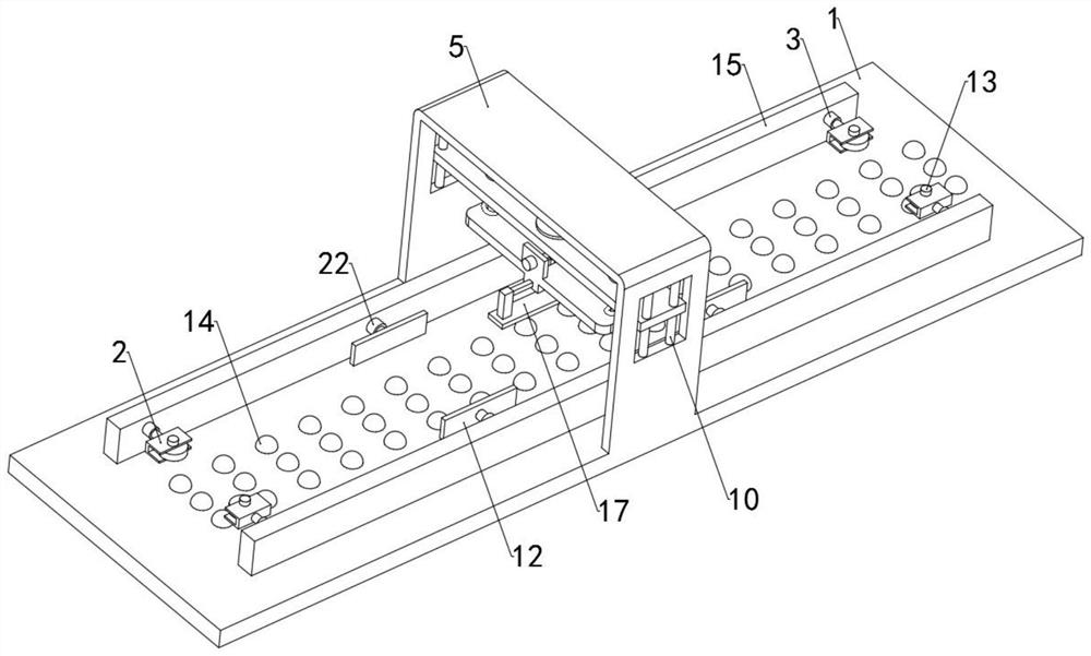
[0031] see figure 2 , The upper surface wall of the operation panel 1 is equipped with balls 14, the balls 14 avoid the friction between the aluminum alloy profiles and the operation panel 1, so that the movement of the aluminum alloy profiles is smoother.

[0032] The difference from Example 1 is that

Embodiment 3

[0034] see figure 1 , the outer walls of both sides of the bracket 5 are provided with a cavity 4, the inside of the cavity 4 is provided with a guide rod 10 that runs through the moving plate 21, the guide rod 10 is fixedly connected with the inner wall of the cavity 4, and the guide rod 10 is connected with the moving plate 21 Sliding fit, the guide rod 10 can limit the moving plate 21 so that the moving plate 21 can only move in the vertical direction.

[0035] The difference from Example 1 is that


PUM


Abstract

The invention discloses a device for grinding a groove of an aluminum alloy profile. The device for grinding the groove of the aluminum alloy profile comprises an operation plate, an inverted-U-shaped support is fixed to the top of the operation plate, a hydraulic rod, a movable plate and a buffer plate are arranged in an inner cavity of the support from top to bottom, and stand columns penetrate through the movable plate. According to the device for grinding the groove of the aluminum alloy profile, aluminum alloy is placed on the top of the operation plate, the aluminum alloy is clamped and fixed through electric push rods and limiting plates, the movable plate and the buffer plate can be pushed downwards through arrangement of the hydraulic rod, a grinding strip attaches to the inner wall of the groove of the aluminum alloy under the action of springs, a roller rotates through arrangement of a motor II and a transmission shaft, under the action of a connecting rod and a protrusion, a moving rod drives a connecting block and the grinding strip to move back and forth, and thus automatic grinding of the inner wall of the aluminum alloy groove is achieved. Compared with a traditional manual grinding mode, the technical scheme has the advantages that the labor amount of workers is reduced, the automation degree is higher, the grinding efficiency is higher, and the large-scale production requirement can be met.

Description

technical field [0001] The invention relates to the technical field of aluminum alloy production and processing, in particular to an aluminum alloy profile groove grinding device. Background technique [0002] my country is a big industrial country. With the advancement of science and technology, my country's manufacturing industry is booming, the economy is becoming stronger and stronger, and new technologies and materials are constantly emerging. Among them, one of the aluminum alloys, such as aluminum-magnesium alloys, has excellent mechanical properties and chemical properties. , Widely used in various fields, in order to ensure that the aluminum alloy is not corroded by the outside world, the surface of the aluminum alloy needs to be treated before leaving the factory, especially the treatment of the groove on the aluminum alloy profile. [0003] In the prior art, the grooves of aluminum alloy profiles are usually polished by hand-held grinding devices. This grinding met...

Claims


Application Information

Patent Timeline
IPC IPC(8): B24B19/02B24B41/06B24B47/14B24B47/12B24B41/00B24B41/02
CPCB24B19/02B24B41/06B24B47/14B24B47/12B24B41/007B24B41/02B24B41/005
Inventor 刘宗意
Owner 湖南千源铝业有限公司
Why Eureka
Try Eureka