Motor shaft conveying device

A technology for conveying devices and motor shafts, which is applied in the direction of conveyor objects, transportation and packaging, and devices for coating liquid on the surface, which can solve the problems that the motor shaft cannot be detected

Active Publication Date: 2021-09-10
常州市昌隆电机股份有限公司
View PDF5 Cites 2 Cited by
  • Summary
  • Abstract
  • Description
  • Claims
  • Application Information

AI Technical Summary

Problems solved by technology

[0004] In order to solve the problem that the current motor shaft cannot be detected during the conveying process, the present invention provides a motor shaft conveying device, including:

Method used


Image

  • Motor shaft conveying device
  • Motor shaft conveying device
  • Motor shaft conveying device

Examples


Embodiment 1

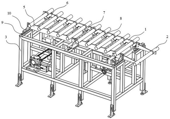
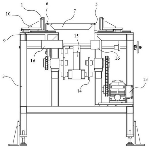
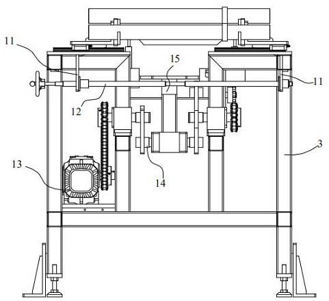
[0038] Such as Figure 1~8 As shown, a motor shaft conveying device includes: a support frame 3, a fixed frame 1 movably installed on the support frame 3, a propulsion mechanism movably arranged between the support frames 3 and a driving mechanism for driving the A driving device for the circular motion of the propulsion mechanism, and

[0039] The fixing frame 1 is provided with several installation grooves 4, and the motor shaft 2 is installed in the installation grooves 4;

[0040] Described propulsion mechanism comprises left movable plate 5, right movable plate 6 and oiling bin 7, and described oiling bin 7 is hinged between described left movable plate 5 and right movable plate 6, and described left movable plate 5 and right movable plate Movable plate 6 is respectively connected with two driving mechanisms by transmission, and the positions of several said oiling bins 7 correspond to several said installation grooves 4 one by one, and said left movable plate 5 and right ...


PUM


Abstract

The invention relates to a motor shaft conveying device. The motor shaft conveying device comprises supporting frames, a fixing frame which is movably installed on the supporting frames, a propelling mechanism which is movably arranged between the supporting frames and a driving device which is used for driving the propelling mechanism to do circular motion, a plurality of installation grooves are formed in the fixing frame, and motor shafts are installed in the installation grooves. The motor shaft conveying device is simple in structure, the motor shafts can slide leftwards or rightwards through lifting of a left movable plate and a right movable plate, in ingenious cooperation with the installation grooves, lantern rings on the motor shafts are detected by utilizing the installation grooves, and meanwhile oiling treatment is carried out on the motor shafts by utilizing left-right sliding of the motor shafts.

Description

technical field [0001] The invention relates to the technical field of mechanical tooling, in particular to a motor shaft conveying device. Background technique [0002] Energy saving and environmental protection have gradually become one of the hot issues in the world, and the world's motors are also developing in the direction of high efficiency and energy saving, with huge development potential. All developed countries have successively formulated energy efficiency standards for motors. Developed countries such as Europe and the United States have continuously improved the access standards for motor energy efficiency, and basically all use high-efficiency and energy-saving motors, and some regions have begun to use ultra-high-efficiency and energy-saving motors. In 2012, the global high-efficiency and energy-saving motors were mainly produced in Asia and Europe, accounting for 60.8% of the global total output. The production areas in Asia are mainly concentrated in Chin...

Claims


Application Information

Patent Timeline
Patent Type & Authority Applications(China)
IPC IPC(8): B65G47/74B05C1/02B05C11/10
CPCB65G47/74B05C1/02B05C11/1039
Inventor 王建南高昱黄丽萍王璐颖
Owner 常州市昌隆电机股份有限公司
Why Eureka
Try Eureka