Concrete support mounting structure and mounting and dismounting method

A technology for installing structures and concrete, which is applied in basic structure engineering, excavation, construction, etc., and can solve problems such as high construction cost, easy to be poured in concrete, and difficult demolition

Pending Publication Date: 2021-09-10
中建八局轨道交通建设有限公司
View PDF0 Cites 1 Cited by
  • Summary
  • Abstract
  • Description
  • Claims
  • Application Information

AI Technical Summary

Problems solved by technology

However, during the implementation of this method, the steel plate is easily poured into the concrete, making it difficult to remove, and the removed concrete support cannot be reused
[0004] In addition, in the prior art, the wire saw cutting method is usually used to cut the connecting steel bars. This method needs to hang the wire saw to the support position, the movement rate is high, and many equipment and personnel need to be coordinated. Not only the construction cost is high, but also Great impact on construction period and low safety

Method used


Image

  • Concrete support mounting structure and mounting and dismounting method
  • Concrete support mounting structure and mounting and dismounting method
  • Concrete support mounting structure and mounting and dismounting method

Examples


Embodiment approach

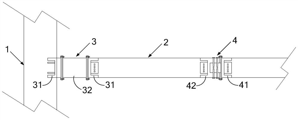
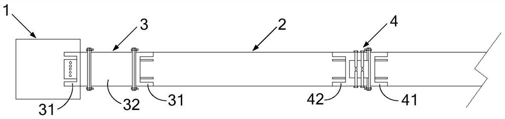
[0057] First preferred embodiment: the second joint assembly 4 also includes a first connecting bolt 43; the protruding portion 413 is provided with a threaded hole 414 for screwing the first connecting bolt 43; the groove portion 423 is provided with There is a through hole 424 through which the first connecting bolt 43 passes.

[0058] Specifically, the protruding portion 413 and the groove portion 423 are both rectangular, and at least one threaded hole 414 is provided on four surfaces of the protruding portion 413, and each threaded hole 414 is located on a corresponding surface. The centerline of the groove part 423 extends to the inside of the protruding part 413 in a direction perpendicular to the corresponding surface, and the four inner walls of the groove part 423 are provided with the through holes 424 at positions corresponding to the threaded holes 414. When the protruding portion 413 is inserted into the groove portion 423, the axes of all the through holes 424 c...


PUM


Abstract

The invention relates to a concrete support mounting structure and a mounting and dismounting method. The mounting structure comprises a first joint assembly and a plurality of second joint assemblies, wherein the first joint assembly comprises two first joints; each first joint comprises a first base and a first anchoring plate vertically fixed on the first side of the first base; the two first anchoring plates are anchored into a crown beam and a concrete support respectively; a butt joint section is detachably connected between the second sides of the two first bases; the plurality of second joint assemblies are connected between every two adjacent concrete support sections in the spliced concrete support in a one-to-one correspondence manner; each second joint assembly comprises a second joint and a third joint; each second joint comprises a second base and a second anchoring plate which is vertically fixed on the first side of the second base and is anchored to the corresponding concrete support section; a convex part is formed on the second side of each second base; each third joint comprises a third base and a third anchoring plate which is vertically fixed on the first side of the third base and is anchored to the corresponding concrete support section; and a groove part for inserting the corresponding convex part is formed on the second side of each third base. The concrete support mounting structure is convenient to mount and dismount and can be repeatedly used.

Description

technical field [0001] The invention relates to the field of foundation pit construction, in particular to a concrete support installation structure and an installation and disassembly method. Background technique [0002] In the construction of municipal deep foundation pit engineering, there are many concrete supports. [0003] For the demolition of concrete support, the existing technology is mainly to add a detachable steel plate in the middle of the concrete support before concrete pouring, and then remove the connecting steel bar in the space of the steel plate after removing the steel plate to achieve the purpose of removing the concrete support . However, during the implementation of this method, the steel plate is easily poured into the concrete, which makes it difficult to remove, and the removed concrete support cannot be reused. [0004] In addition, in the prior art, the wire saw cutting method is usually used to cut the connecting steel bar. This method needs...

Claims


Application Information

Patent Timeline
Patent Type & Authority Applications(China)
IPC IPC(8): E02D17/04
CPCE02D17/04
Inventor 雷友明车家伟徐茂虎殷涛李文鹏刘晓刚冯树岩李佳龙
Owner 中建八局轨道交通建设有限公司
Why Eureka
Try Eureka