
Power head special for gas lift and pump suction of reverse circulation drilling machine

A reverse circulation, power head technology, applied in rotary drilling rigs, drilling equipment and methods, drilling tools, etc., can solve the problems of high maintenance cost, lack of power head installation and reinforcement, and short service life.

Pending Publication Date: 2021-09-10
江苏金亚益重工科技有限公司
View PDF0 Cites 0 Cited by
  • Summary
  • Abstract
  • Description
  • Claims
  • Application Information

AI Technical Summary

Problems solved by technology

[0005] In view of the problems existing in the prior art, the object of the present invention is to provide a special power head for gas lift and pump suction of reverse circulation drilling rigs, which solves the problem of the existing special power heads for gas lift and pump suction of reverse circulation drilling rigs. When in use, Usually there is no mechanism for limiting the position and anti-skewing of the power head, and there is no mechanism for installing and reinforcing the power head, and there is no mechanism for quick and convenient disassembly and assembly of the mandrel of the power head, resulting in gas lift of the reverse circulation drilling rig Compared with the special power head for pump suction, the working efficiency is poor, the service life is short, and the disassembly and assembly are inconvenient, the stability is low, and the maintenance cost is high in the later period.

Method used


Image

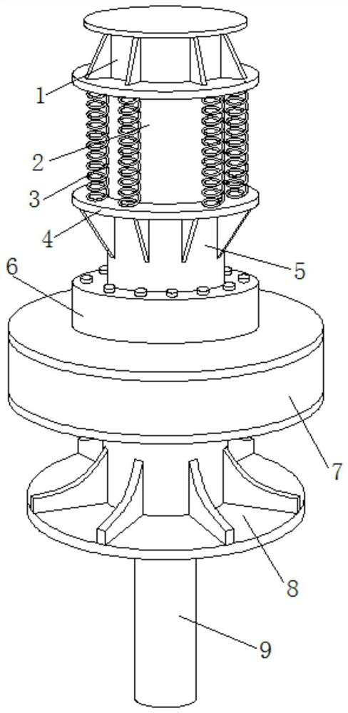
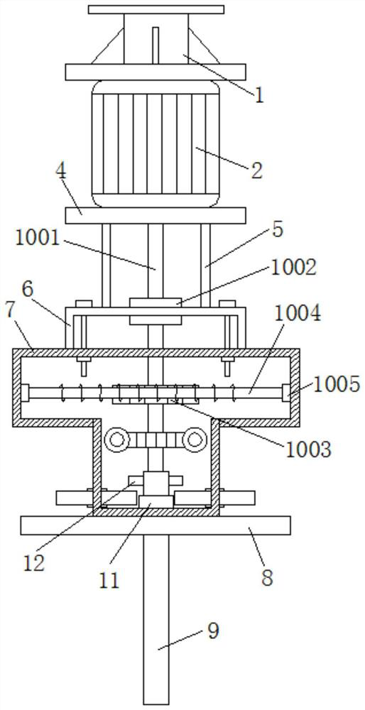
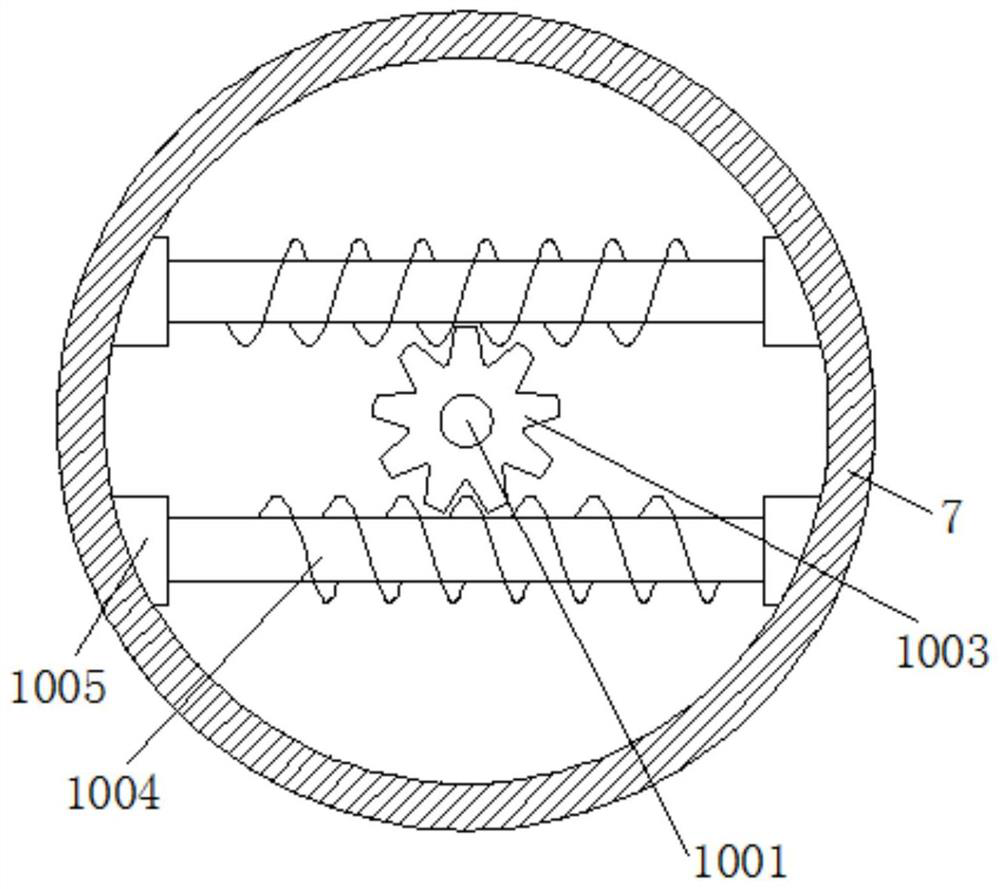
  • Power head special for gas lift and pump suction of reverse circulation drilling machine
  • Power head special for gas lift and pump suction of reverse circulation drilling machine
  • Power head special for gas lift and pump suction of reverse circulation drilling machine

Examples


Embodiment Construction

[0031] The following will be combined with the accompanying drawings in the embodiments of the present invention; the technical solutions in the embodiments of the present invention will be clearly and completely described; obviously; the described embodiments are only some embodiments of the present invention; rather than all embodiments, based on The embodiments in the present invention; all other embodiments obtained by those skilled in the art without creative work; all belong to the protection scope of the present invention.

[0032] In the description of the present invention, it should be noted that the orientations or positional relationships indicated by the terms "upper", "lower", "inner", "outer", "top / bottom" etc. are based on the orientations shown in the drawings Or positional relationship is only for the convenience of describing the present invention and simplifying the description, but does not indicate or imply that the device or element referred to must have ...


PUM


Abstract

The invention discloses a power head special for gas lift and pump suction of a reverse circulation drilling machine, and belongs to the field of reverse circulation drilling machines. The power head special for the gas lift and pump suction of the reverse circulation drilling machine comprises a top plate, the bottom end of the top plate is fixedly connected with a driving motor, and the outer wall of the driving motor is provided with a damping spring. According to the power head, by arranging a limiting and stabilizing mechanism, under the action of a bearing arranged on the outer wall of a rotating rod, the rotating rod is more stable when rotating at the top of a side plate, and the rotating quality of the rotating rod is guaranteed; under the action of worms arranged in a shell, the rotating rod drives the worms to rotate through a first gear disc, and through two sets of symmetrically-arranged worms, the worms rotate on the outer wall of the first gear disc, the first gear disc is limited, and therefore it is guaranteed that the rotating position of the rotating rod is accurate, and the rotating rod is prevented from inclining and deviating in long-term work; and the structure is simple, operation is convenient, the working quality of the rotating rod is guaranteed, and the service life of the rotating rod is prolonged.

Description

technical field [0001] The invention relates to the field of reverse circulation drilling rigs, in particular to a special power head for gas lift and pump suction of the reverse circulation drilling rig. Background technique [0002] The reverse circulation drilling rig is driven by the rotary device of the drilling rig to rotate the drill pipe and the drill bit to break the rock and soil, and then use the reverse circulation slag discharge method, that is, when drilling, the mud passes through the wellhead from the mud pool, enters the bottom of the well in a self-retained manner, and is then entrained Cuttings return to the wellhead through the hollow drill pipe, and are discharged to the mud pool through the faucet and the slag discharge pipe. After the sediment settles, it flows back into the well for circulation. The force of the lifting system is used to pressurize and lift the drilling tool to achieve the purpose of drilling. [0003] The existing special power head...

Claims


Application Information

Patent Timeline
Patent Type & Authority Applications(China)
IPC IPC(8): E21B3/02E21B12/00E21B17/07E21B41/00
CPCE21B3/02E21B12/00E21B17/07E21B41/00
Inventor 陆长春郭继华陆文娟胡志伟葛宏林京
Owner 江苏金亚益重工科技有限公司
Learn More