Roots blower impeller clearance adjusting tool and adjusting method

A Roots blower and impeller clearance technology, which is applied to mechanical equipment, machines/engines, liquid fuel engines, etc., and can solve problems such as inconvenient adjustment of impeller clearances

Pending Publication Date: 2021-09-10
上海钰捷机械有限公司
0 Cites 0 Cited by

AI-Extracted Technical Summary

Problems solved by technology

[0004] In view of the above problems, the object of the present invention is to provide a Roots fan impeller gap a...

Method used

[0028] The spacer is provided with a V-shaped section 12, and the V-shaped section 12 is provided with an oblique screw hole 13, and the adjusting screw 14 is loaded into the oblique screw hole 13. The rotation of the second impeller is restricted by the adjusting screw 14 , and the directi...

Abstract

The invention discloses a Roots blower impeller clearance adjusting tool and an adjusting method. The tool comprises a limiting piece capable of stretching into an air hole of a Roots blower shell, and the length of the limiting piece is larger than the diameter of the air hole; and a limiting part for limiting rotation of a first impeller is arranged at the lower end of the limiting piece, an adjusting screw rod used for abutting against a second impeller and limiting rotation of the second impeller is arranged on the limiting piece, and the limited rotation direction of the second impeller is the same as the limited rotation direction of the first impeller. By the adoption of the tool, the state of the optimal fit clearance between the two impellers can be fixed, then the positions of a gear, an impeller shaft and a bearing are fixed, and the problem that in the prior art, a clearance between two impellers can be changed is solved.

Application Domain

Rotary piston pumpsRotary piston liquid engines +2

Technology Topic

ImpellerIndustrial engineering +1

Image

  • Roots blower impeller clearance adjusting tool and adjusting method
  • Roots blower impeller clearance adjusting tool and adjusting method
  • Roots blower impeller clearance adjusting tool and adjusting method

Examples

  • Experimental program(1)

Example Embodiment

[0023] The technical solutions of the present invention will be described below with reference to the accompanying drawings. Obviously, the described embodiments are merely embodiments, and not all of the embodiments; and the structures shown in the accompanying drawings are merely schematic, and does not represent the real thing. It should be noted that all other embodiments obtained by those of ordinary skill in the art will belong to the scope of the present application based on these embodiments in the present invention.
[0024] It is to be noted that the term "including" or any other variable in this article is intended to cover non-exclusive containe, so that the processes, methods, items, or devices including a series of elements include not only those elements, but also not clear Other elements listed, or include elements inherent for such processes, methods, items, or equipment. In the absence of more limitations, the elements defined by the statement "include a ..." and do not exclude additional identical or equivalents in the process, method, article, or apparatus including the element.
[0025] The term "upper", "lower", "inside", "outside" does not constitute an absolute spatial relationship limit, is just a relative position. This is understandable to those skilled in the art.
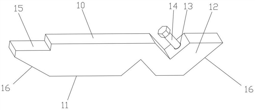
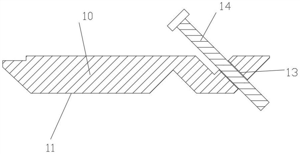
[0026] See Figure 1-3 The Roots fan wheel gap adjustment tool, including the restricted member 10, the shape of the restricted member 10 is a long barphone shape. Limit 10 is a metal member, integrated processing. The limiting element is greater than the diameter of the air hole (intake port 21 or exhaust port 22) of the Roots fan housing; the limit piece can be in the wind in which the Roots fan housing is extended.
[0027] The lower end of the limit piece is provided with a limit portion 11 that limits the first impeller rotation, in the present embodiment, the height of the limit member 10 is greater than the minimum gap of the first impeller and the air hole. That is, the lower end of the limit member 10 is the limit portion 11. Of course, the limit portion 11 can also adopt a downwardly protruding projection.
[0028] A V-section 12, the V-section 12 position is provided on the limit piece, and the adjustment screw 14 is fitted into the inclined screw 13. The second impeller rotation is restricted by adjusting the screw 14, and the second impeller is limited to the direction of the first impeller to limit the rotation. Adjust the screw tilt setting, facilitate the side of the second impeller to increase the contact area.
[0029] The upper surface of the limit piece is provided with a step 15 that is fitted to the air intake port 21 of the Roots fan housing. When the limit seat is held upward by the first impeller, the step 15 card acts at the edge of the intake port 21. The limit direction of the step 15 is opposite to the limit direction of the adjustment screw 14.
[0030] Further, the two ends of the limit member 10 are provided with an inner inclined edge 16 that prevents the impeller.
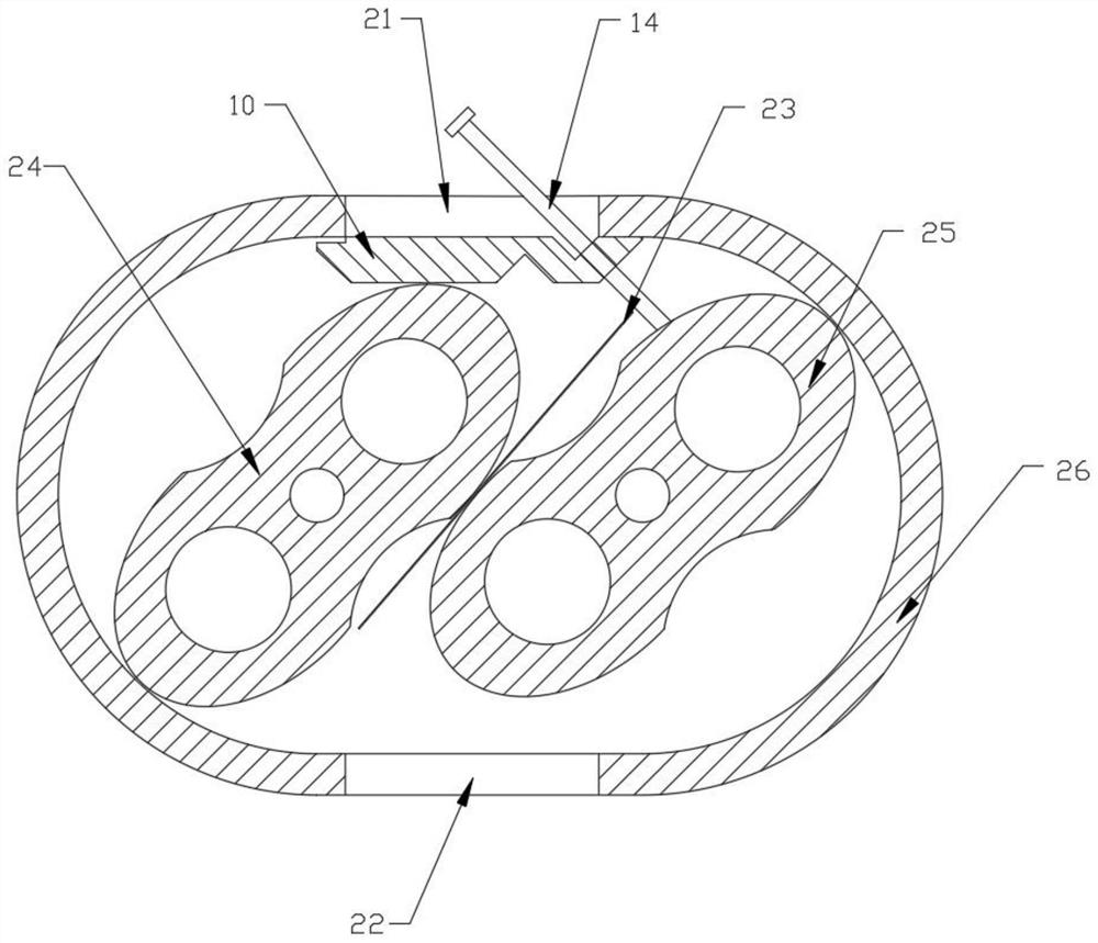
[0031] See image 3 , Roots Straw Assembly Tuning Adjustment Method, including the following steps:
[0032] A, first mounted two impellers (24, 25), bearings, and gears, after adjusting the position of the two impelings (as soon as possible to til as one side of the two impellers), plug the plug 23 between the two impellers. Inside the gap;
[0033] B. Put the limit piece 10 into the air intake port 21 in the Roots fan housing 26 (or the housing can be inverted, placed in the air outlet) position, and the limit piece 10 is disposed in the leaf radial direction. Above the two impellers, by rotating the impeller shaft, the first impeller 24 therein causes the restricted member 10 until both ends of the limit member 10 are held by the edge of the air hole;
[0034] C. By tightening the adjusting screw 14 such that the screw is adjusted to hold the second impeller 25 such that the second impeller 25 cannot rotate the same direction as the first impeller is limited; at this time, the plug is clamped in two impellers. between;
[0035] D, fixed gear, impeller shaft, bearing position;
[0036] E, loosen the adjustment screw 14, remove the Roots fan wheel gap adjustment tool, remove the plug of the plug 23.
[0037] The basic principles, main features, and the advantages of the present invention are shown and described above. Those skilled in the industry will be appreciated that the present invention is not limited by the above embodiments, and the above-described embodiments and description are only the principles of the invention, and there will be various kinds of present invention without departing from the spirit and scope of the invention. Changes and improvements, these changes and improvements have fallen within the scope of the invention claims. The scope of the invention is defined by the appended claims and equivalents thereof.

PUM

no PUM

Description & Claims & Application Information

We can also present the details of the Description, Claims and Application information to help users get a comprehensive understanding of the technical details of the patent, such as background art, summary of invention, brief description of drawings, description of embodiments, and other original content. On the other hand, users can also determine the specific scope of protection of the technology through the list of claims; as well as understand the changes in the life cycle of the technology with the presentation of the patent timeline. Login to view more.
Why Eureka
Try Eureka