Auxiliary cooling water pump structure of nuclear power plant

A technology for auxiliary cooling and nuclear power plants. It is applied in the direction of pumps, pump devices, pump components, etc. It can solve the problems of large overall flexibility of the shaft system, excessive vibration of the motor in the auxiliary cooling water system, and insufficient stability of the structure.

Pending Publication Date: 2021-09-10
LIAONING HONGYANHE NUCLEAR POWER
View PDF0 Cites 2 Cited by
  • Summary
  • Abstract
  • Description
  • Claims
  • Application Information

AI Technical Summary

Problems solved by technology

[0002] In the prior art, the structure of the auxiliary cooling water pump for nuclear power plants mainly has the following defects: 1. The coupling and the pump shaft are integrated into one structure, so that only the non-drive end bearing of the motor in the pump shaft is subjected to axial force and the shafting is only in the Motor drive end and drive end radial displacement with bearing constraints
2. Due to the long total length of the shaft, which is about 2690mm, the relatively small number of supports leads to a large overall flexibility of the shaft system, resulting in an unstable structure
3. The existing structure also has the problem that the overall support stiffness of the shaft system is weak
[0003] In addition, the auxiliary cooling water pump structure of the conventional nuclear power plant adopted by Unit 1 of Hongyanhe Nuclear Power Plant, since the commissioning began, the motors of the auxiliary cooling water system of each unit frequently vibrate beyond the standard

Method used


Image

  • Auxiliary cooling water pump structure of nuclear power plant
  • Auxiliary cooling water pump structure of nuclear power plant
  • Auxiliary cooling water pump structure of nuclear power plant

Examples


Embodiment Construction

[0017] The following will clearly and completely describe the technical solutions in the embodiments of the present invention with reference to the accompanying drawings in the embodiments of the present invention. Obviously, the described embodiments are only some, not all, embodiments of the present invention. Based on the embodiments of the present invention, all other embodiments obtained by persons of ordinary skill in the art without creative efforts fall within the protection scope of the present invention.

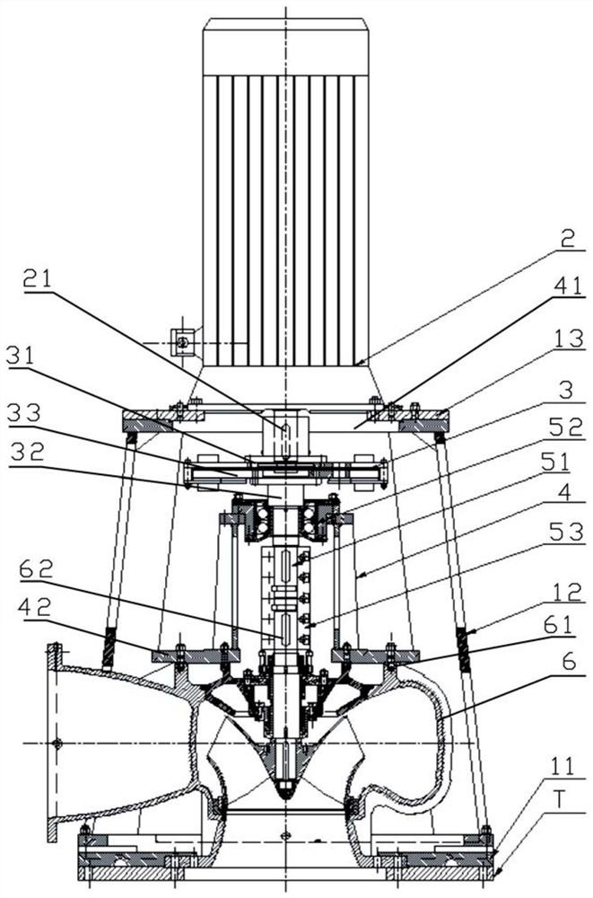
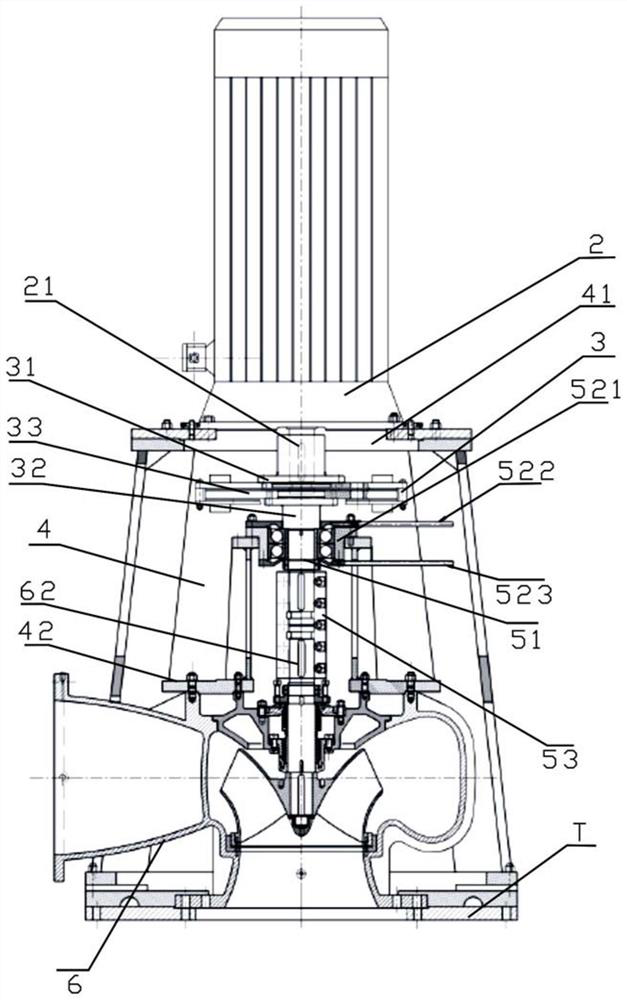
[0018] see in conjunction Figure 1-Figure 2 Shown is Embodiment 1 of the nuclear power plant auxiliary cooling water pump structure of the present invention.

[0019] The auxiliary cooling water pump structure of the nuclear power plant in this embodiment includes: a motor support for fastening on the ground foundation plate T, and the motor support includes: a bottom plate for fastening the bottom of the water pump 6 on the ground foundation plate T 11. The brac...


PUM


Abstract

The invention discloses an auxiliary cooling water pump structure of a nuclear power plant. The auxiliary cooling water pump structure comprises a motor support, a motor, a bearing bracket, a transmission stabilizing shaft and a load shaft; the motor support comprises a bottom plate, a support and a top plate; the motor is fastened on the top plate, and a motor shaft of the motor is connected to a conductor disc; the transmission stabilizing shaft is connected to a pump shaft of a water pump; and the load shaft is connected to one end of the transmission stabilizing shaft, the load shaft is connected to a permanent magnet disc, and the conductor disc and the permanent magnet disc form an asynchronous permanent magnet coupling structure, wherein a thrust bearing is installed on the bearing bracket, installed on the periphery of the transmission stabilizing shaft and is used for bearing axial force generated in operation of the water pump and gravity of the pump shaft in a shutdown state. According to the auxiliary cooling water pump structure of the nuclear power plant, axial force generated in the pump movement process and the gravity of a rotor in the shutdown state can be independently borne; and a vibration transmission path is cut off, and resonant frequency is avoided.

Description

technical field [0001] The invention relates to the field of nuclear power appliances, in particular to a nuclear power plant auxiliary cooling water pump structure. Background technique [0002] In the prior art, the structure of the auxiliary cooling water pump for nuclear power plants mainly has the following defects: 1. The coupling and the pump shaft are integrated into one structure, so that only the non-drive end bearing of the motor in the pump shaft is subjected to axial force and the shafting is only in the The drive end of the motor and the drive end have bearing-constrained radial displacement. 2. Due to the long total length of the shaft, which is about 2690mm, the relatively small number of supports leads to a large overall flexibility of the shaft system, resulting in an unstable structure. 3. The existing structure also has the problem of weak overall support stiffness of the shaft system. [0003] In addition, the auxiliary cooling water pump structure of ...

Claims


Application Information

Patent Timeline
Patent Type & Authority Applications(China)
IPC IPC(8): F04D13/06F04D29/044F04D29/046F04D29/66F04D29/60H02K5/00H02K49/10
CPCF04D13/06F04D29/044F04D29/046F04D29/669F04D29/605H02K5/00H02K49/108
Inventor 王季能耿佳扬刘政
Owner LIAONING HONGYANHE NUCLEAR POWER
Why Eureka
Try Eureka