Unlock instant, AI-driven research and patent intelligence for your innovation.
Energy-saving control method for fixed-frequency refrigeration equipment
What is Al technical title?
Al technical title is built by PatSnap Al team. It summarizes the technical point description of the patent document.
A technology for energy-saving control and refrigeration equipment, which is applied in the direction of refrigerators, refrigeration components, refrigeration and liquefaction, etc., and can solve the problem that fixed-frequency compressors cannot drive multiple loads
Pending Publication Date: 2021-09-10
NANJING NORMAL UNIVERSITY
View PDF0 Cites 0 Cited by
Summary
Abstract
Description
Claims
Application Information
AI Technical Summary
This helps you quickly interpret patents by identifying the three key elements:
Problems solved by technology
Method used
Benefits of technology
Problems solved by technology
[0003] In order to solve the defect in the prior art that multiple loads cannot be driven by a fixed-frequency compressor, the present invention proposes an energy-saving control method for fixed-frequency refrigeration equipment
Method used
Image
Click on the blue label to locate the original text in one second.
Reading with bidirectional positioning of images and text.
Examples
Embodiment 1
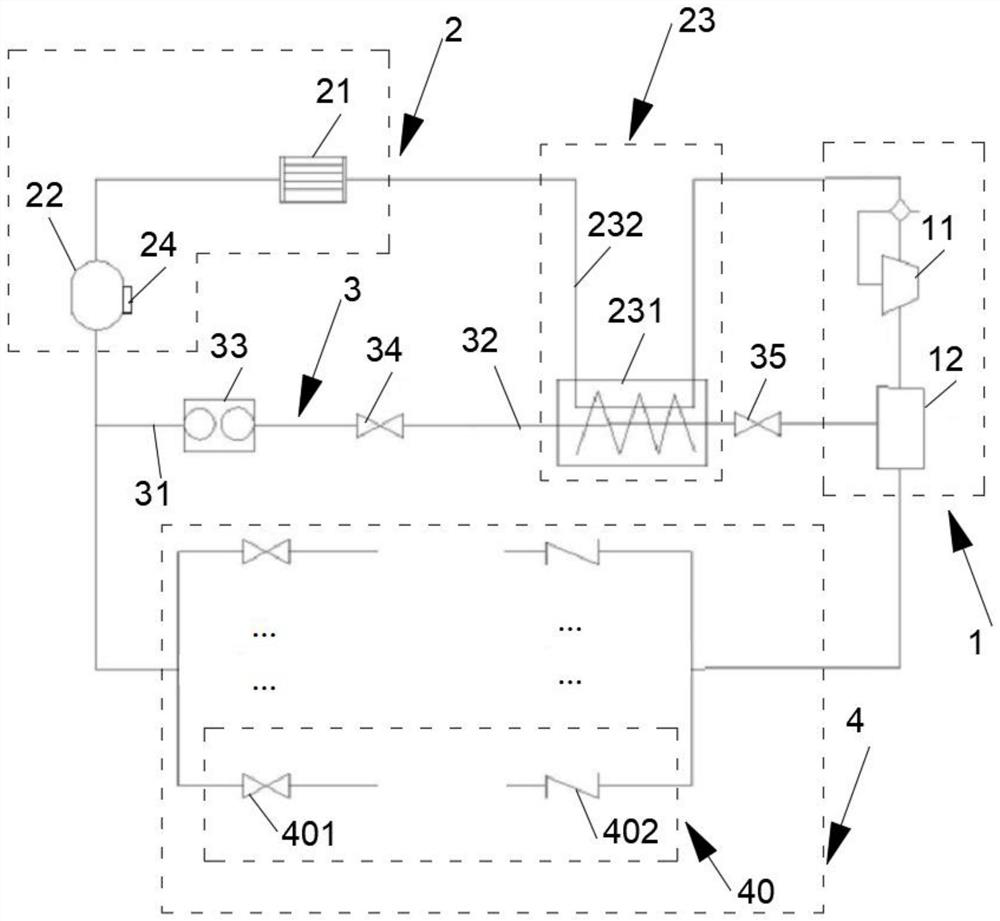
[0078] The refrigerant circulation circuit in this embodiment adopts the first liquid evaporation part 23 , and the load connection part 4 of the device includes three evaporation units 40 .
[0079] In this embodiment, the load connecting portion 4 is connected with three evaporators, namely evaporator A, evaporator B and evaporator C. Before the equipment works, the ambient temperature of the environment where the evaporator A, the evaporator B and the evaporator C are located is all between 35°C and 43°C.
[0080] In this embodiment, taking the opening degree of the first valve 34 as the flow control value, the corresponding relationship between the number of effective loads and the working state of the first valve 34 is shown in Table 1 below.
[0081] Table 1: Correspondence between the number of effective loads and the working state of the first valve 34
[0082] Payload Quantity The opening degree of the first valve 34 3 0 2 3 1 3 / 4
[0...
Embodiment 2
[0088] The refrigerant circulation circuit in this embodiment adopts the second liquid vaporizing part 23 , and the load connection part 4 of the device includes three evaporating units 40 .
[0089] In this embodiment, the load connecting portion 4 is connected with three evaporators, namely evaporator A, evaporator B and evaporator C. Before the equipment works, the ambient temperature of the environment where the evaporator A, the evaporator B and the evaporator C are located is all between 35°C and 43°C.
[0090] In this embodiment, taking the working state of the third valve 235 as the flow control value, the corresponding relationship between the effective load quantity and the working state of the third valve 235 is shown in Table 1 below.
[0091] Table 1: Correspondence between the number of effective loads and the working state of the third valve 235
[0092] Payload Quantity Working state of the third valve 235 3 cut off 2 Intermittent condu...
PUM
Abstract
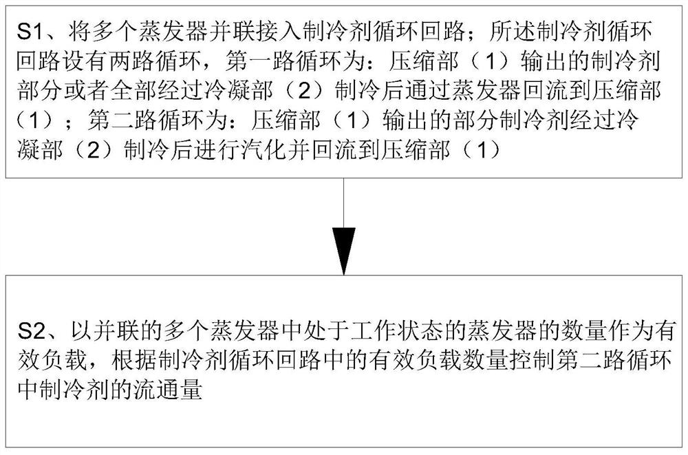
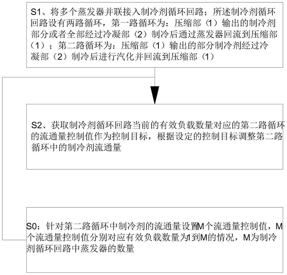
The invention discloses an energy-saving control method for fixed-frequency refrigeration equipment. A plurality of evaporators are connected into a refrigerant circulation loop in parallel; the refrigerant circulation loop is provided with two paths of circulation; the first path of circulation is that a refrigerant output by a compression part is refrigerated by a condensation part and then flows back to the compression part through the evaporators; the second path of circulation is that the refrigerant output by the compression part is vaporized after being refrigerated by the condensation part and flows back to the compression part; and the number of the evaporators in the working state in the plurality of evaporators connected in parallel serves as effective loads, and the circulation amount of the refrigerant in the second-path circulation is controlled according to the number of the effective loads in the refrigerant circulation loop. According to the constant-frequency compressor, the number of the effective loads in the first-path circulation and the circulation amount of the refrigerants in the second path of circulation are correspondingly adjusted, so that dynamic balance of the air inflow of the input end of the compression part is guaranteed, and a foundation is laid for driving the plurality of loads, namely evaporators through one constant-frequency compressor.
Description
technical field [0001] The invention relates to the field of refrigeration equipment, in particular to an energy-saving control method for fixed-frequency refrigeration equipment. Background technique [0002] With the development of the economy, refrigeration equipment plays an increasingly important role in the process of food preservation, and the performance and energy saving of compression condensing units used for refrigeration have attracted more and more attention. Among the compression condensing units currently used for refrigeration, the multi-connected type is mainly realized by using the variable frequency compressor to drive multiple loads or multiple compressors are placed in one unit to control multiple loads respectively, while the fixed frequency compressor controls two loads. It is rare that there are more than one load. This is mainly because when the fixed-frequency compressor controls multiple loads, the cooling capacity required by the load is small an...
Claims
Application Information
Patent Timeline
Application Date:The date an application was filed.
Publication Date:The date a patent or application was officially published.
First Publication Date:The earliest publication date of a patent with the same application number.
Issue Date:Publication date of the patent grant document.
PCT Entry Date:The Entry date of PCT National Phase.
Estimated Expiry Date:The statutory expiry date of a patent right according to the Patent Law, and it is the longest term of protection that the patent right can achieve without the termination of the patent right due to other reasons(Term extension factor has been taken into account ).
Invalid Date:Actual expiry date is based on effective date or publication date of legal transaction data of invalid patent.

