Automatic deslagging device of pipeline, heat exchanger pipe and self-cleaning method

A technology for automatic slag removal and heat exchanger tube application in the field of pipeline cleaning, which can solve problems such as insufficient cleaning and cleanliness due to easy wear and tear of screw devices.

Pending Publication Date: 2021-09-10
WUHAN IRON & STEEL GRP ECHENG IRON & STEEL CO LTD
View PDF5 Cites 2 Cited by
  • Summary
  • Abstract
  • Description
  • Claims
  • Application Information

AI Technical Summary

Problems solved by technology

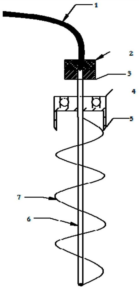
[0005] The object of the present invention is to provide an automatic slag removal device for pipelines, especially a self-cleaning automatic slag removal device for air preheaters, s...

Method used


Image

  • Automatic deslagging device of pipeline, heat exchanger pipe and self-cleaning method
  • Automatic deslagging device of pipeline, heat exchanger pipe and self-cleaning method
  • Automatic deslagging device of pipeline, heat exchanger pipe and self-cleaning method

Examples


Embodiment Construction

[0029] The technical solutions of the present invention will be clearly and completely described below in conjunction with the embodiments. Obviously, the described embodiments are part of the embodiments of the present invention, but not all of them. Based on the embodiments of the present invention, all other embodiments obtained by persons of ordinary skill in the art without making creative efforts belong to the protection scope of the present invention.

[0030] In describing the present invention, it should be understood that the terms "center", "longitudinal", "transverse", "upper", "lower", "front", "rear", "left", "right", " The orientations or positional relationships indicated by "vertical", "horizontal", "top", "bottom", "inner" and "outer" are based on the orientations or positional relationships shown in the drawings, and are only for the convenience of describing the present invention and Simplified descriptions, rather than indicating or implying that the devic...


PUM


Abstract

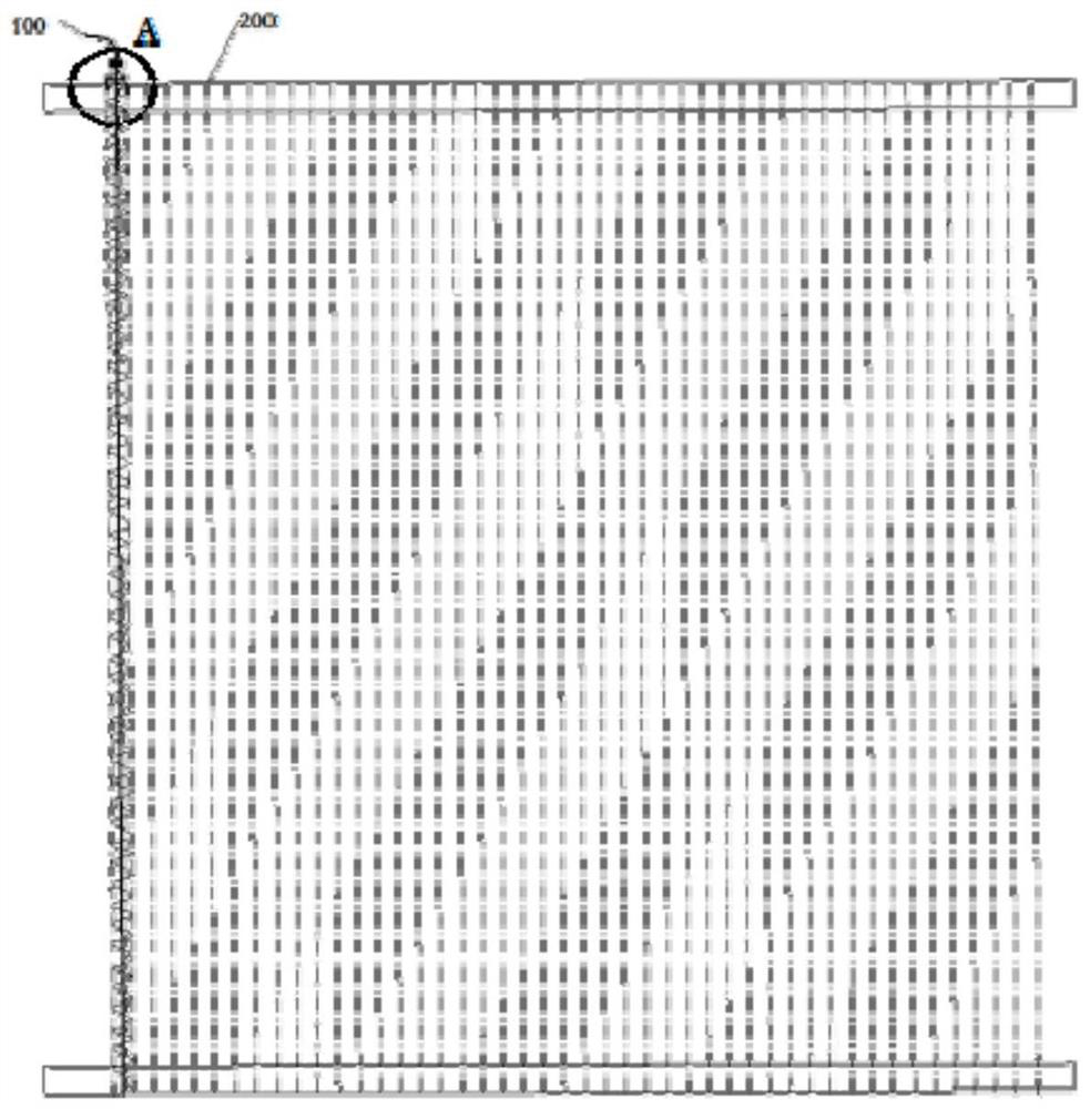
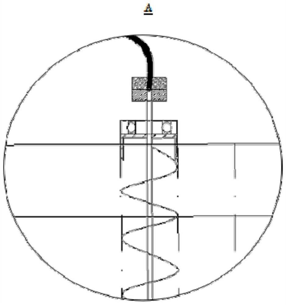
The invention provides an automatic deslagging device of a pipeline, a heat exchanger pipe and a self-cleaning method, in particular to an automatic deslagging device capable of achieving self cleaning for an air preheater. The automatic deslagging device comprises a rotary deslagging mechanism and a cleaning mechanism. The outer edge of the rotary deslagging mechanism is matched with the inner diameter of the pipeline and rotates under the driving of fluid in the pipeline so as to deslag the inner wall of the pipeline. The cleaning mechanism is used for cleaning the rotary deslagging mechanism and/or the inner wall of the pipeline so as to solve the technical problems that in the prior art, furnace shutdown for deslagging is needed, a spiral device is prone to being abraded, or the cleaning cleanliness is not enough.

Description

technical field [0001] The invention relates to the technical field of pipeline cleaning, in particular to an automatic slag removal device for pipelines, a heat exchanger tube for automatic slag removal and a self-cleaning method. Background technique [0002] At present, gas-fired boilers in iron and steel plants mainly use blast furnace gas, coke oven gas, and converter gas as fuel. After the gas is burned in the furnace, it is discharged to the atmosphere after heat exchange through the air preheater pipeline. Because the gas contains more or less impurities, its main components are dust, sulfide, nitrogen oxides, etc. When these impurities flow through the air preheater pipeline, they will adhere to the inner surface of the pipeline, and the equipment will gradually increase after long-term operation, so that the air preheater pipeline will be blocked, resulting in a decrease in heat exchange capacity and a decrease in boiler thermal efficiency. [0003] The common pra...

Claims


Application Information

Patent Timeline
IPC IPC(8): F28G3/10F28G15/04F28G9/00
CPCF28G3/10F28G15/04F28G9/00
Inventor 刘金彪盛志钧贾文召刘震寰
Owner WUHAN IRON & STEEL GRP ECHENG IRON & STEEL CO LTD
Why Eureka
Try Eureka