Automatic wafer centering method

An automatic centering and wafer technology, applied in the manufacture of conveyor objects, electrical components, semiconductor/solid-state devices, etc., can solve the problem of reducing equipment production capacity and equipment space utilization, low precision, and inability to achieve real-time monitoring of wafers, etc. question

Pending Publication Date: 2021-09-10
SHENYANG KINGSEMI CO LTD
View PDF0 Cites 3 Cited by
  • Summary
  • Abstract
  • Description
  • Claims
  • Application Information

AI Technical Summary

Problems solved by technology

[0003] 1) The mechanical centering unit is centered by mechanical clamping, and its disadvantage is that the accuracy is low (±0.2mm)
[0004] 2) The optical centering unit mainly processes the wafer through optical measurement, and its disadvantage is that the centering speed is relatively slow
[0005] 3) Regardless of whether m

Method used


Image

  • Automatic wafer centering method
  • Automatic wafer centering method
  • Automatic wafer centering method

Examples


Embodiment Construction

[0051] In order to make the above objects, features and advantages of the present invention more obvious and understandable, the specific implementation methods of the present invention will be described in detail below in conjunction with the accompanying drawings. In the following description, numerous specific details are set forth in order to provide a thorough understanding of the present invention. However, the present invention can be implemented in many other ways different from those described here, and those skilled in the art can make similar improvements without violating the connotation of the invention, so the present invention is not limited by the specific implementation disclosed below.

[0052]Unless otherwise defined, all technical and scientific terms used herein have the same meaning as commonly understood by one of ordinary skill in the technical field of the invention. The terminology used herein in the description of the invention is for the purpose of ...


PUM


Abstract

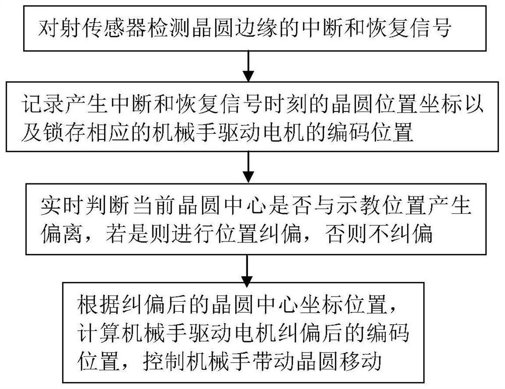
The invention discloses an automatic wafer centering method, which comprises the following steps of: acquiring a wafer edge signal by a sensor in the process of taking back a wafer by a manipulator, obtaining the current center position of the wafer through an algorithm, comparing the current center position of the wafer with the teaching center position of the wafer, and compensating in the process of sending out the wafer next time by the manipulator if a deviation exists; and when the wafer gap just falls in one sensor detection area, rejecting the measurement result of the sensor in the gap area through an algorithm. According to the method, a machine table does not need to additionally increase stations, a mechanical arm can measure and compensate the wafer offset in the wafer conveying process, the equipment productivity is not affected at all, and the cost is far lower than that of a traditional mechanical centering unit and an optical centering unit.

Description

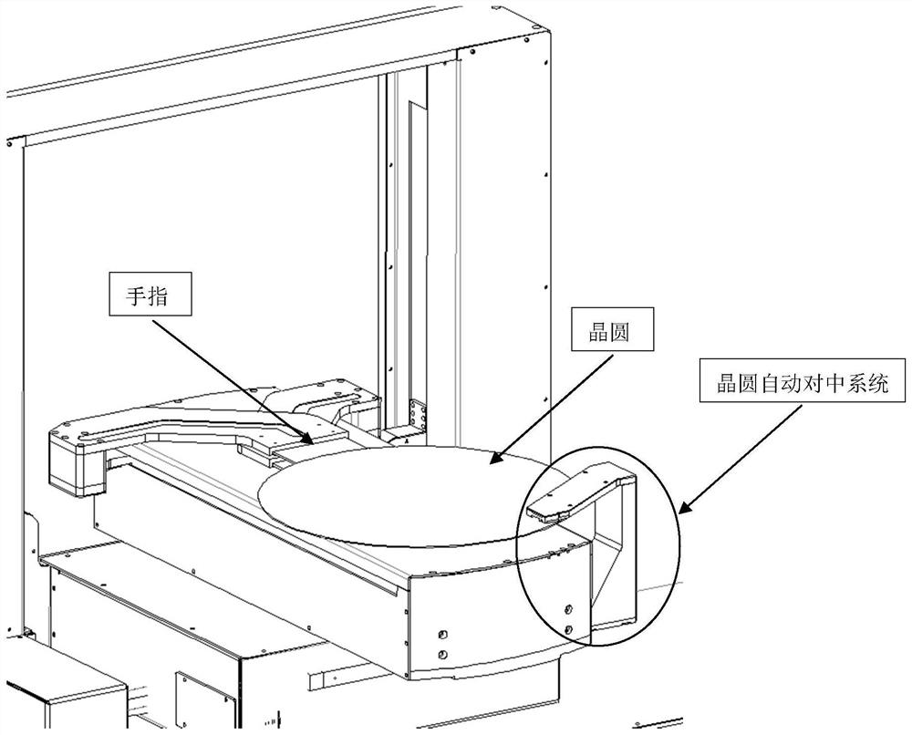
technical field [0001] The invention belongs to the field of electronic semiconductors, in particular to an automatic wafer centering method. Background technique [0002] In electronic semiconductor production and processing equipment, the wafer handling manipulator is responsible for the transfer of wafers between various stations. It is the core moving part of the machine. Its positioning accuracy directly determines the accuracy of wafer placement. The accuracy of the placement position determines the yield rate of chip processing. Therefore, it is particularly important to improve the accuracy of manipulator wafer pick-and-place. In order to improve the accuracy of the wafer placement by the manipulator, before the wafer is sent into the key process unit, such as before entering the glue uniform unit, the wafer is first put into the mechanical or optical centering unit, which can ensure that each time the wafer is sent into the process The chips of the unit are all lo...

Claims


Application Information

Patent Timeline
IPC IPC(8): H01L21/68H01L21/67H01L21/677
CPCH01L21/681H01L21/67706H01L21/67253
Inventor 吴天尧杨磊
Owner SHENYANG KINGSEMI CO LTD
Why Eureka
Try Eureka