Synchronous bulb control system and synchronous control bulb

A technology for control systems and light bulbs, applied in electrical components and other directions, which can solve problems such as response differences, timing deviations, and irregularities of light-emitting units.

Pending Publication Date: 2021-09-10
ZHANGZHOU GO WIN LIGHTING CO LTD
View PDF0 Cites 0 Cited by
  • Summary
  • Abstract
  • Description
  • Claims
  • Application Information

AI Technical Summary

Problems solved by technology

[0003] In the traditional control scheme, the supporting control unit is mostly controlled according to the number of LED lights. Since multiple control units control multiple LED light-emitting unit schemes, there will be response differences due to the synchronization of the control units, so that after a period of use, each control unit There is a large deviation in the timing of the light-emitting unit, and the light emitted by the light-emitting unit appears to be out of order; although there are also bulbs on the market that use a control chip to control multiple LED lights to turn on and off, but once it loses user access control, There will be disordered LED light emission, and automatic regular adjustment cannot be realized

Method used


Image

  • Synchronous bulb control system and synchronous control bulb
  • Synchronous bulb control system and synchronous control bulb
  • Synchronous bulb control system and synchronous control bulb

Examples


Embodiment 1

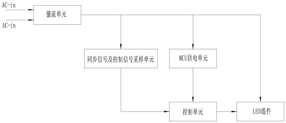
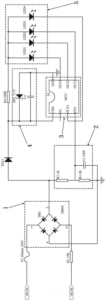
[0038] Such as figure 1 or figure 2 Shown, a kind of synchronous bulb control system of the present invention comprises:

[0039] The rectification unit 1 is connected to an external power supply line and rectifies and outputs the input power supply current;

[0040] The synchronization signal and control signal sampling unit 2 is connected to the rectification unit 1 and is used for counting the number of times and periods of periodic changes of alternating current or control signal pulses to provide synchronization signals and collect control signals input by an external controller;

[0041] The control unit 3 is connected to the synchronization signal and control signal sampling unit 2, and receives the synchronization signal and / or control signal output by the synchronization signal and control signal sampling unit 2;

[0042] The MCU power supply unit 4 is connected to the rectification unit 1 and the control unit 3 respectively and is used to supply power to the contr...

Embodiment 2

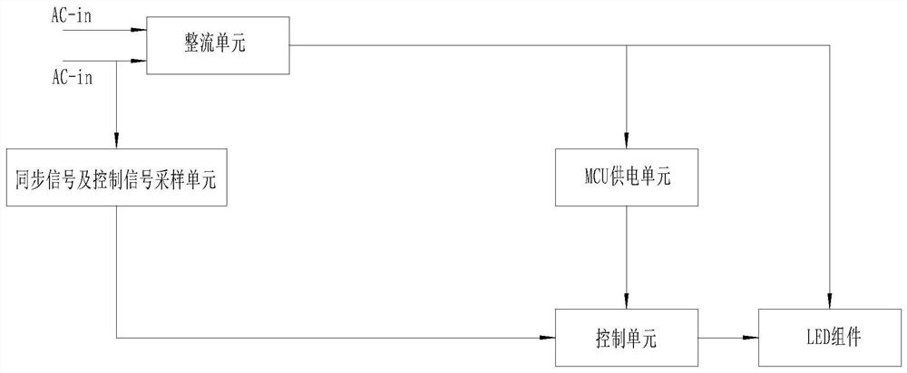
[0063] Such as image 3 As shown, this embodiment is roughly the same as Embodiment 1, the difference is that in this embodiment, the synchronous signal and control signal sampling unit is connected to the external power supply line and used to count the periodic changes of alternating current or control signal pulses Times and periods to provide synchronization signals and collect control signals input by external controllers.

[0064] The rest of the connection relationship and the general control mechanism of this embodiment are substantially the same as those of Embodiment 1, and will not be repeated here.


PUM


Abstract

The invention discloses a synchronous bulb control system and a synchronous control bulb. The synchronous bulb control system comprises a rectification unit, a synchronous signal and control signal sampling unit, a control unit, an MCU power supply unit and an LED assembly. The rectification unit is connected with an external power supply line. The synchronous signal and control signal sampling unit is connected with the rectification unit or an external power supply line and is used for counting the frequency and period of a periodic change of an alternating current or a control signal pulse so as to provide a synchronizing signal and collect a control signal input by an external controller; the control unit receives the synchronizing signal and the synchronizing signal and/or the control signal output by the control signal sampling unit; the MCU power supply unit is respectively connected with the rectification unit and the control unit and is used for supplying power to the control unit; and the LED assembly comprises one or more LED units, the LED assembly is respectively connected with the rectification unit and the control unit and is controlled by the control unit. The scheme is reliable in implementation, high in synchronization efficiency and good in use stability.

Description

technical field [0001] The invention relates to the field of light bulb control devices and light bulbs, in particular to a synchronous light bulb control system and a synchronous control light bulb. Background technique [0002] As an important lighting tool, light bulbs are widely used for indoor decoration and atmosphere creation in public places. Since decorative light bulbs are mostly composed of multiple LEDs connected in series, in order to enable the LEDs to be synchronously controlled according to certain rules, usually , the designer will carry out lighting control according to the corresponding functional requirements with the matching light bulb control system, such as light-dark, marquee effects, etc. [0003] In the traditional control scheme, the supporting control unit is mostly controlled according to the number of LED lights. Since multiple control units control multiple LED light-emitting unit schemes, there will be response differences due to the synchron...

Claims


Application Information

Patent Timeline
Patent Type & Authority Applications(China)
IPC IPC(8): H05B45/30H05B45/50H05B45/34H05B45/32
CPCH05B45/30H05B45/50H05B45/34H05B45/32
Inventor 吴青安黄雅莹
Owner ZHANGZHOU GO WIN LIGHTING CO LTD
Why Eureka
Try Eureka