Automatic guide device for calcaneal sustentaculum talus screw

A calcaneal-carrying talus process, automatic guidance technology, applied in medical science, surgery, fixation, etc., can solve problems such as error, operation failure, secondary damage, etc.

Active Publication Date: 2021-09-14
THE FIRST AFFILIATED HOSPITAL OF MEDICAL COLLEGE OF XIAN JIAOTONG UNIV
View PDF6 Cites 0 Cited by
  • Summary
  • Abstract
  • Description
  • Claims
  • Application Information

AI Technical Summary

Problems solved by technology

However, in clinical operation, if there are not enough suitable auxiliary equipment, even under X-ray positioning, it is very difficult to achieve reasonable positioning and puncture fixation on both sides of the sacrum.
For doctors with insufficient operating experience, the implementation of this operation is a clinical problem
In particular, there are flexor hallucis longus tendon and neurovascular tissues under the trocar process, if the puncture operation is inaccurate and inappropriate, it will lead to unnecessary secondary damage, or even catastrophic medical injury
[0004]According to the above, although there is already a guide for bone-loaded talar process screws in clinical operations to assist in guiding and positioning, but it is simple in structure and completely depends on the human body. Manual operation will inevitably produce errors caused by human factors, which will lead to unsatisfactory positioning of the sacral screw, which will affect the surgical effect, and in severe cases, the operation will fail; at the same time, it is difficult for the traditional bone-screw guide Quantification and display cannot be scientifically quantified and cannot provide detailed and standardized data reference for follow-up operations. In view of the above problems, it is necessary to design an automatic guiding device for calcaneal talus screws

Method used


Image

  • Automatic guide device for calcaneal sustentaculum talus screw
  • Automatic guide device for calcaneal sustentaculum talus screw
  • Automatic guide device for calcaneal sustentaculum talus screw

Examples


Embodiment Construction

[0026] In the following text, numerous specific details are set forth in order to provide a thorough understanding of the concepts underlying the described embodiments, however, it will be apparent to those skilled in the art that the described embodiments can be used without these specific details. Some or all instances were practiced, and in other instances well-known process steps were not described in detail.

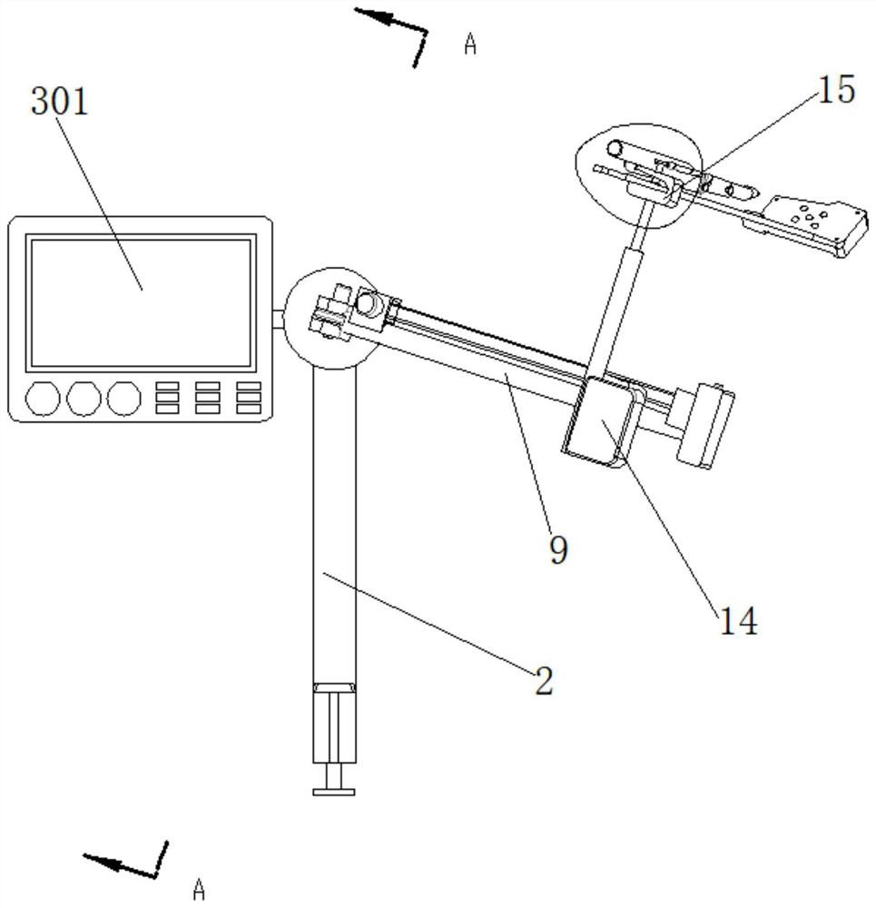
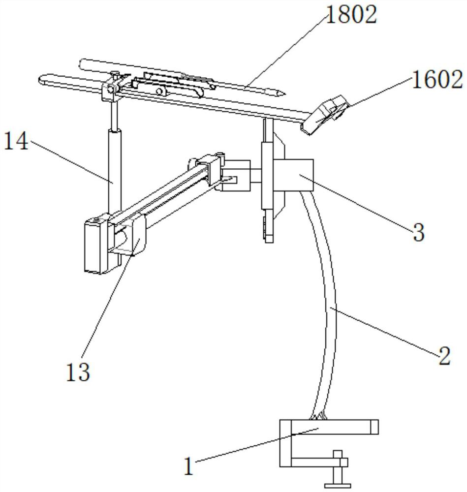
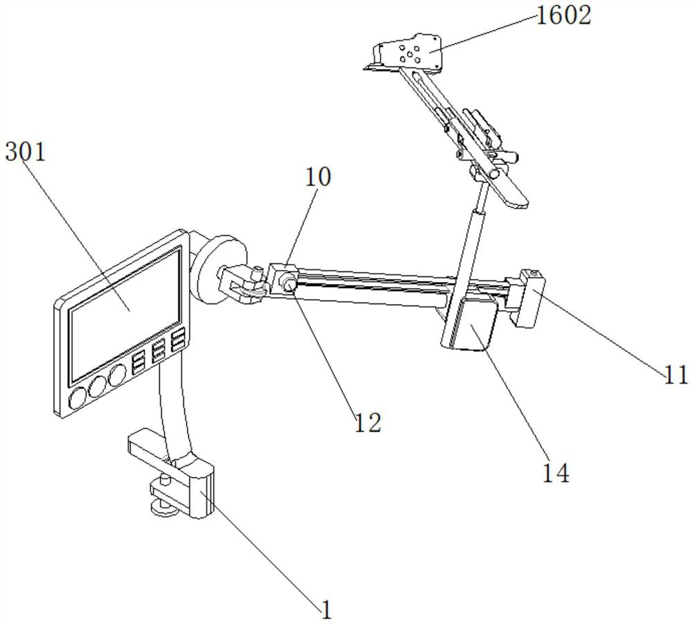
[0027] like figure 1 , figure 2 , image 3 , Figure 4 , Figure 5 , Image 6 , Figure 7 , Figure 8 , Figure 9As shown in the figure, an automatic guiding device for calcaneous calcaneal screws includes a deck 1, a support plate 2, an A stepping motor 3, an A rotating shaft 4, a fixing seat 5, a B stepping motor 6, a B rotating shaft 7, and a rotating disk 8. Guide rod 9, fixed cover 10, angle sensor 11, C stepping motor 12, adjustment block 13, electric push rod 14, clamping plate 15, guide assembly 16, locking assembly 17, drilling mechanism 18, descri...


PUM


Abstract

The invention discloses an automatic guide device for a calcaneal sustentaculum talus screw. The automatic guide device comprises a clamping seat, a supporting plate, a stepping motor A, a rotating shaft A, a fixed seat, a stepping motor B, a rotating shaft B, a rotating disc, a guide rod, a fixed cover, an angle sensor, a stepping motor C, an adjusting block, an electric push rod, a clamping plate, a guide assembly, a locking assembly and a drilling mechanism. Firstly, through a three-axis electric mechanism, accurate secondary correction can be conveniently carried out within a small range, and the operation difficulty is reduced; secondly, a kirschner wire drilling mechanism is combined, so that after the position is determined, manual drilling is not needed, and the intermediate operation is optimized; and finally, the position and the angle are judged through a fixed base point, so that medical staff can conveniently master the final three-axis specific position of a guide hole by observing a display, and the scientific quantification of operation is realized. In addition, a traditional guide device and a rear end device can be fixed in an ingenious mode, so that the clinical practicability is finally expanded, and the popularization and application of the orthopedics department are facilitated.

Description

technical field [0001] The invention relates to the field of orthopedic surgical instruments, in particular to an automatic guiding device for calcaneal-loaded talus screws. Background technique [0002] Calcaneal fracture is a common type of fracture in orthopedics. It is characterized by severe pain in the heel, obvious swelling and ecchymosis, inability to walk on the heel, and calcaneal tenderness as the main manifestations. It is often injured by falling or crushing from a high place, and if the fracture is poorly healed or malunion, it can easily lead to the occurrence of traumatic osteoarthritis. [0003] At present, with the development of modern medical technology, more and more attention has been paid to the good curative effect and broad prospects of minimally invasive internal fixation surgery for calcaneal fractures. However, the anatomy of the calcaneus is very complex. In three dimensions, there are multiple joint axes, and the surface structure is three-dime...

Claims


Application Information

Patent Timeline
Patent Type & Authority Applications(China)
IPC IPC(8): A61B17/90
CPCA61B17/88A61B2560/0462A61B2560/0456
Inventor 王莹杨卫周李达
Owner THE FIRST AFFILIATED HOSPITAL OF MEDICAL COLLEGE OF XIAN JIAOTONG UNIV
Why Eureka
Try Eureka