
Hot punching automatic forging and pressing compound die structure and hot punching automatic forging and pressing compound die process

A compound mold and red punch technology, applied in forging presses, forging presses, forging/pressing/hammer devices, etc., can solve problems such as inability to realize automation, uncontrollable product flash, and lack of pre-clamping force

Pending Publication Date: 2021-09-14
张连松 +1
View PDF0 Cites 0 Cited by
  • Summary
  • Abstract
  • Description
  • Claims
  • Application Information

AI Technical Summary

Problems solved by technology

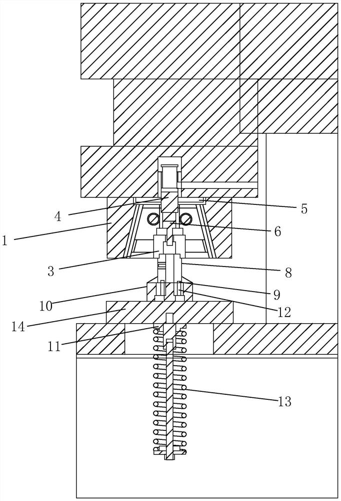
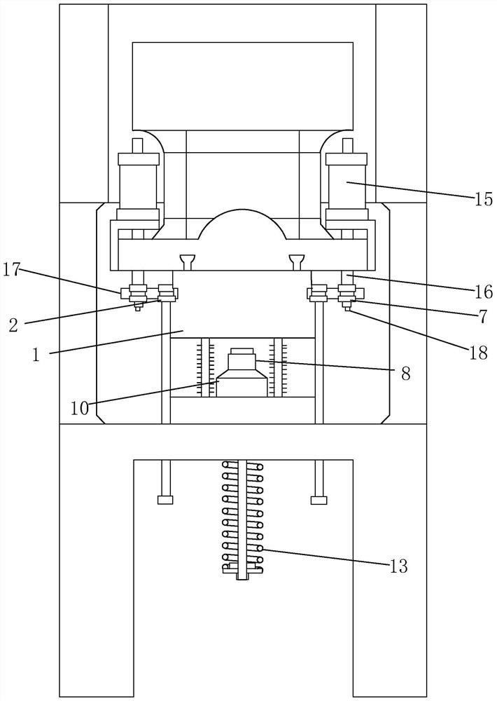
[0002] With the development of equipment manufacturing, robotics, automobile manufacturing, electronic technology and automation technology, especially the "Made in China 2025" planning automatic red punch is moving towards high processing adaptability, high production efficiency, highly automated control, and high economic benefits The current development of the mold mechanism for automatic red punching machines has the following problems: 1. Some hardware products do not need to be brought out through the upper mold, and the efficiency of the lower mold clamping and discharging is low and complicated, so that automation or automation efficiency cannot be realized Low; 2. Mold, mold frame, and main slider. In the stamping process below, foam, impurities, and oil are deposited on the mold, mold frame, and main slider, resulting in product defects, and the mold cannot be well cooled and lubricated. The extrusion model has rounded corners, so it needs to be replaced frequently; 4. The main slider slides into the mold frame by self-generated gravity, without pre-clamping force, resulting in uncontrollable product flash

Method used


Image

  • Hot punching automatic forging and pressing compound die structure and hot punching automatic forging and pressing compound die process
  • Hot punching automatic forging and pressing compound die structure and hot punching automatic forging and pressing compound die process
  • Hot punching automatic forging and pressing compound die structure and hot punching automatic forging and pressing compound die process

Examples


Embodiment Construction

[0044] The technical solutions in the embodiments of the present invention will be clearly and completely described and discussed below in conjunction with the accompanying drawings of the present invention. Obviously, what is described here is only a part of the examples of the present invention, not all examples. Based on the present invention All other embodiments obtained by persons of ordinary skill in the art without creative efforts fall within the protection scope of the present invention.

[0045] In order to facilitate the understanding of the embodiments of the present invention, specific embodiments will be taken as examples for further explanation below in conjunction with the accompanying drawings, and each embodiment does not constitute a limitation to the embodiments of the present invention.

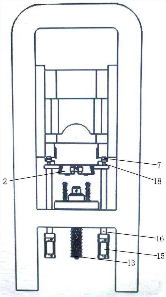
[0046] Embodiment 1 of the present invention refers to figure 1 Section structure and Figure 4As shown in the forging structure, the upper die structure is adopted, an...


PUM


Abstract

The invention relates to a hot punching automatic forging and pressing compound die structure and a hot punching automatic forging and pressing compound die process. The hot punching automatic forging and pressing compound die structure comprises an upper die, a lower die and a demolding mechanism, the upper die is an open die, the lower die is a spring die, the upper die and the lower die are extruded and closed through a punch press to perform forging and pressing forming on a metal brass material, and the demolding mechanism separates a formed blank from the upper die and the lower die. According to the hot punching automatic forging and pressing compound die structure, a complex discharging mechanism is omitted, the pre-locking die force is increased, a traditional half die structure is divided into two parts, feeding ports are reduced, the service life of the die is prolonged, stamping products are free of flashes due to the fact that a die cavity is mounted, the manual trimming procedure is omitted, the purpose of finish machining visual sorting automation is achieved, hot punching automation type composite die forging operation can be achieved, and the working efficiency is improved.

Description

technical field [0001] The invention relates to the technical field of red punch forging, in particular to a red punch automatic forging composite die structure and its technology. Background technique [0002] With the development of equipment manufacturing, robotics, automobile manufacturing, electronic technology and automation technology, especially the "Made in China 2025" planning automatic red punch is moving towards high processing adaptability, high production efficiency, highly automated control, and high economic benefits The current development of the mold mechanism for automatic red punching machines has the following problems: 1. Some hardware products do not need to be brought out through the upper mold, and the efficiency of the lower mold clamping and discharging is low and complicated, so that automation or automation efficiency cannot be realized Low; 2. Mold, mold frame, and main slider. In the stamping process below, foam, impurities, and oil are deposit...

Claims


Application Information

Patent Timeline
Patent Type & Authority Applications(China)
IPC IPC(8): B21J13/02B21J13/03B21J5/02B21J9/00B21J3/00B21K29/00
CPCB21J13/02B21J13/03B21J5/02B21J9/00B21J3/00B21K29/00
Inventor 张连松陈政
Owner 张连松
Learn More