Shearing machine for lens production and processing

A shearing machine and lens technology, applied in metal processing, stone processing tools, stone processing equipment, etc., can solve problems such as increasing difficulty and cycle, affecting shearing quality, and fan blade collision.

Active Publication Date: 2021-09-14
南通山森光学科技有限公司
View PDF8 Cites 1 Cited by
  • Summary
  • Abstract
  • Description
  • Claims
  • Application Information

AI Technical Summary

Problems solved by technology

[0003] According to the invention with the publication number CN111923132B: a lens shearing machine, the motor drives the bristles to clean up the debris on the shelf, and the debris falls into the interior of the shelf through the second chute and the third chute, while the first rotating shaft The rotation drives the fan blades to rotate, and the rotation of the fan blades generates suction to absorb the debris in the storage plate. The debris enters the dust collection frame through the first chute, and flows out of the dust collection frame through the through groove, which is convenient for cleaning and collecting lens debris. But there are also some deficiencies: as the current lens is often curved around after processing, but in this invention, the shearing track of the shearing machine is not described, which increases the difficulty and cycle of post-processing; Without any treatment, it is easy to collide with the fan blades and cause damage to the fan blades; finally, in the process of continuous shearing, the shearing knives tend to generate a lot of heat. If the temperature is not cooled in time, the Affect the subsequent cutting quality

Method used


Image

  • Shearing machine for lens production and processing
  • Shearing machine for lens production and processing
  • Shearing machine for lens production and processing

Examples


Embodiment Construction

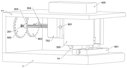
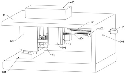
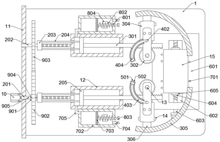
[0026] refer to Figure 1-6 , a shearing machine for lens production and processing, comprising a base 1 and a lens 15, a support plate 11 is fixed on the base 1, the support plate 11 has an inverted L-shaped structure, a box body 12 is symmetrically fixed on the inner wall of the top of the support plate 11, and the box body The inner wall of 12 is slidably connected with a shearing mechanism, and the inner wall of the box 12 is slidably connected with a driving mechanism;

[0027] The shearing mechanism includes a rack 301 slidingly connected to the inner wall of the box body 12. The inner wall of the top of the support plate 11 is rotatably connected to a rotating rod 13. The rotating rod 13 is coaxially fixed with a gear 302. The gear 302 is engaged with the rack 301. The side wall is fixedly connected with a rotating seat 303, the inner wall of the rotating seat 303 is fixedly connected with a support seat 304 by bolts, the bottom wall of the support seat 304 is equipped ...


PUM


Abstract

The invention discloses a shearing machine for lens production and processing. The shearing machine for lens production and processing comprises a base and a lens, a supporting plate is fixedly arranged on the base, the supporting plate is of an inverted-L-shaped structure, box bodies are symmetrically and fixedly arranged on the inner wall of the top of the supporting plate, a shearing mechanism is slidably connected to the inner walls of the box bodies in a penetrating mode, the shearing mechanism comprises a rack slidably connected to the inner walls of the box bodies, rotating rods are symmetrically and rotatably connected to the inner wall of the top of the supporting plate, gears are coaxially and fixedly arranged on the rotating rods, rotating seats are fixedly connected to the side walls of the rotating rods, supporting seats are fixedly connected to the inner walls of the rotating seats through bolts, shearing machine bodies are installed on the bottom walls of the supporting seats, arc-shaped sliding rails are symmetrically and fixedly arranged on the inner wall of the top of the supporting plate, and sliding blocks are fixedly connected to the supporting seats. According to the shearing machine for lens production and machining, the two symmetrically-arranged shearing machine bodies can synchronously carry out shearing work or independently carry out shearing, the shearing track of each shearing machine is in an arc shape, the requirement for lens machining at present is met, and the application range of the shearing machine is widened.

Description

technical field [0001] The invention relates to the technical field of shearing machines, in particular to a shearing machine for lens production and processing. Background technique [0002] Lenses are transparent materials with one or more curved surfaces made of optical materials such as glass or resin. After polishing, they are often assembled with spectacle frames to form glasses, which are used to correct the user's vision and obtain a clear vision. [0003] According to the invention with the publication number CN111923132B: a lens shearing machine, the motor drives the bristles to clean up the debris on the shelf, and the debris falls into the interior of the shelf through the second chute and the third chute, while the first rotating shaft The rotation drives the fan blades to rotate, and the rotation of the fan blades generates suction to absorb the debris in the storage plate. The debris enters the dust collection frame through the first chute, and flows out of th...

Claims


Application Information

Patent Timeline
Patent Type & Authority Applications(China)
IPC IPC(8): B28D1/22B28D7/00B28D7/02B28D7/04B26D11/00B26D7/08B26D7/18B08B15/04
CPCB28D1/22B28D7/00B28D7/02B28D7/04B26D11/00B26D7/08B26D7/1863B08B15/04
Inventor 尹金岳
Owner 南通山森光学科技有限公司
Why Eureka
Try Eureka