Double-step floating burr removing device of crankshafts and machining method

A technology for deburring and crankshafts, which is applied to grinding drives, metal processing equipment, manufacturing tools, etc., can solve the problems of the tool without radial floating function, unstable quality, low efficiency, etc., to achieve a simplified structure and avoid rigidity. Contact, the effect of prolonging the service life

Inactive Publication Date: 2017-04-05
CHANGSHA NORMAL UNIV
View PDF13 Cites 2 Cited by
  • Summary
  • Abstract
  • Description
  • Claims
  • Application Information

AI Technical Summary

Problems solved by technology

The burr on the oil hole on the crankshaft is cleaned with a special machine, but the burr on the small curved surface of the crankshaft balance weight and journal can only be removed manually with a hand-held file
Since manual hand-held grinding tools can only be processed in a single step, and the tool does not have a radial floating function, the efficiency is low and the quality is unstable
However, the mainstream floating spindle on the market uses compressed air as the driving force, and the cost is high.

Method used


Image

  • Double-step floating burr removing device of crankshafts and machining method
  • Double-step floating burr removing device of crankshafts and machining method
  • Double-step floating burr removing device of crankshafts and machining method

Examples


Embodiment 1

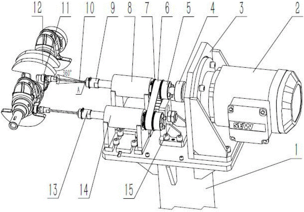
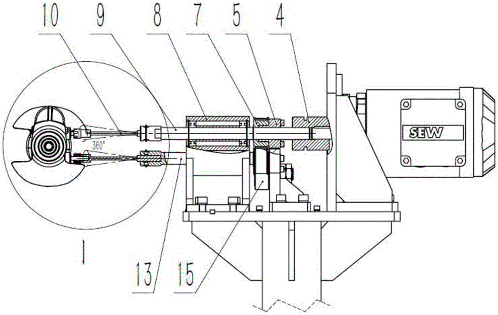
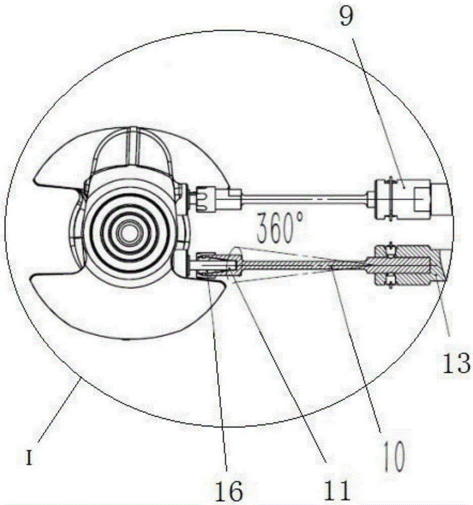
[0042] refer to figure 1 , the preferred embodiment of the present invention provides a crankshaft double-step floating deburring device, including a base 1, a geared motor 2, a motor seat 3, a coupling 4, an expansion sleeve 5, a synchronous belt 6, and a synchronous pulley 7. Main transmission shaft seat 8, main transmission shaft 9, elastic knife bar 10, hair brush 11, auxiliary transmission shaft 13, auxiliary transmission shaft seat 14, tensioning wheel assembly 15 and elastic collet 16.

[0043] The main transmission shaft seat 8 , the auxiliary transmission shaft seat 14 , the motor seat 3 and the tensioning wheel assembly 15 are fixedly installed on the base 1 .

[0044] The geared motor 2 is fixedly installed on the motor base 3 .

[0045] The main transmission shaft 9 is installed on the main transmission shaft seat 8 through a rolling bearing, and its input end is connected with the output shaft of the reduction motor 2 through a shaft coupling 4, and an elastic kn...


PUM


Abstract

The invention discloses a double-step floating burr removing device of crankshafts. The device comprises a speed reduction motor, a coupler, a main drive shaft, an auxiliary transmission shaft, a synchronous belt, a synchronous pulley, flexible cutter bars, brushes and the like, wherein an input end of the main drive shaft is connected to an output shaft of the speed reduction motor, one flexible cutter bar is arranged at an output end of the main drive shaft, an input end of the auxiliary transmission shaft is connected to the input end of the main drive shaft through the synchronous pulley and the synchronous belt, and the other flexible cutter bar is arranged at an output end of the auxiliary transmission shaft. Flexible chucks used for fixedly installing the brushes are arranged in ends of the flexible cutter bars. The device has the effects that the overall structure is simple; the main drive shaft and the auxiliary transmission shaft are connected through the synchronous pulley and the synchronous belt, the rotation driving force from the motor is divided into two parts so as to realize simultaneous feeding machining, and the machining efficiency is improved; and the flexible cutter bars are matched with a robot to remove burrs, rigid contact between cutters and work-pieces is prevented, and the service life of equipment is prolonged. The invention further provides a machining method of the device. The method has the advantages that the machining steps are simplified, and the qualification rate of products is high.

Description

technical field [0001] The invention relates to the technical field of deburring and surface finishing of castings such as cast iron and cast steel, and in particular relates to a crankshaft double-step floating deburring device and a processing method. Background technique [0002] As the key part of the engine, the crankshaft is mostly made of cast iron and cast steel. Due to the many curved surfaces and complex shapes of the crankshaft structure, the burrs after machining are diversified, and there are manufacturing size deviations and fixture positioning errors. Robots are used to automatically remove them. The burrs are likely to cause rigid contact between the tool and the workpiece in part of the machining track, causing damage to the equipment, and at the same time, the removal effect of the burr in the part of the machining track is not ideal. [0003] At present, in many aspects of crankshaft cleaning, it is basically still in the state of manual operation and semi...

Claims


Application Information

Patent Timeline
Patent Type & Authority Applications(China)
IPC IPC(8): B24B9/04B24B41/02B24B47/10
CPCB24B9/04B24B41/02B24B47/10
Inventor 王纪婵陶能如李伟林
Owner CHANGSHA NORMAL UNIV
Why Eureka
Try Eureka