Injection pressure-boosting and speed-increasing structure of die casting machine

The technology of a die casting machine and a pressurized cavity is applied in the field of die casting machines, which can solve the problems of the quality of die castings, the high cost of magnesium alloy die casting machines, and the increase of production costs, and achieve the effects of full castings, simple and reasonable structure, and reliable performance.

Inactive Publication Date: 2015-11-11
佛山联升压铸科技有限公司
View PDF6 Cites 3 Cited by
  • Summary
  • Abstract
  • Description
  • Claims
  • Application Information

AI Technical Summary

Problems solved by technology

[0005] Therefore, magnesium alloy die-casting and magnesium alloy die-casting machines are becoming one of the important research projects in the world today. However, there are still some problems in the magnesium alloy die-casting process, which limits the expansion of its application. Because the heat capacity of magnesium alloy is small, the latent heat of solidification is small. , the solidification process is very different from the traditional aluminum alloy and zinc alloy die-casting. In the die-casting process, a higher filling speed is required to ensure that the magnesium alloy is filled and solidified in a relatively short period of time.
However, due to the backwardness of the domestic magnesium alloy die-casting industry and the high cost of magnesium alloy die-casting machines, many companies still use ordinary die-casting machines to engage in magnesium alloy die-casting, and ordinary die-casting machines are limited by the injection speed, so the quality of the die-castings produced is not only problematic , and can easily lead to accidents
In order to solve the problems caused by the slow injection speed of ordinary die-casting machines, die-casting machine manufacturers at home and abroad have produced special die-casting machines for magnesium alloys, but the price is much higher than ordinary die-casting machines, which increases the production cost, which is not ideal.

Method used


Image

  • Injection pressure-boosting and speed-increasing structure of die casting machine
  • Injection pressure-boosting and speed-increasing structure of die casting machine
  • Injection pressure-boosting and speed-increasing structure of die casting machine

Examples


Embodiment Construction

[0019] The present invention will be further described below in conjunction with the accompanying drawings and embodiments.

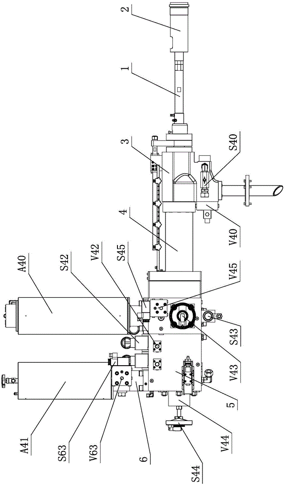
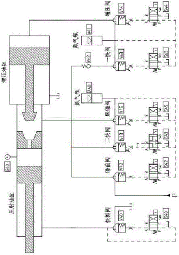
[0020] see figure 1 , figure 2 , the injection pressurization and speed-up structure of the die-casting machine includes an injection punch 1, one side of the injection punch 1 is provided with an injection part 2, and the other side of the injection punch 1 is sequentially provided with an injection cylinder 3 , the injection piston rod 4 and the booster cylinder 5, a booster chamber is formed between the injection piston rod 4 and the booster cylinder 5; the booster cylinder 5 is provided with a fast oil block assembly and two fast oil block assemblies components.

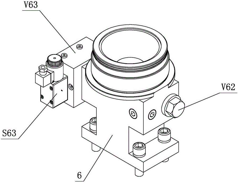
[0021] A fast oil circuit block assembly includes a fast oil circuit seat 6, a fast valve V63, a fast pilot valve S63 and a one-way valve V62; The cavities communicate with each other, and a fast valve V63, a fast pilot valve S63 and a one-way valve V62 are respectively arranged on a f...


PUM


Abstract

The invention discloses an injection pressure-boosting and speed-increasing structure of a die casting machine. The injection pressure-boosting and speed-increasing structure comprises an injection punch, wherein an injection part is arranged at one side of the injection punch; an injection oil cylinder, an injection piston rod and a pressure-boosting oil cylinder are sequentially arranged at the other side of the injection punch; a pressure-boosting cavity is formed between the injection piston rod and the pressure-boosting oil cylinder; and a primarily quick oil path block assembly and a secondarily quick oil path block assembly are arranged on the pressure-boosting oil cylinder. According to the injection pressure-boosting and speed-increasing structure, the speed of the primarily quick action and the secondarily quick action is increased by a design method and a control mode which are combined with a practical production process, so that requirements of producing thin-wall parts such as a magnesium alloy mobile phone middle plate and the like are met, and a common horizontal type cold chamber die casting machine is transformed into a special die casting machine for thin-wall parts represented by the die-cast magnesium alloy mobile phone middle plate; the modified die casting machine can realize that cast pieces are full, less in shrinkage cavities, smooth in surface, good in smoothness, free of flow marks, less in flanges, free of air bubbles and flaws and high in practicability, and meet processing requirements.

Description

technical field [0001] The invention relates to a die-casting machine, in particular to an injection pressurization speed-increasing structure of a die-casting machine. Background technique [0002] Die-casting is the abbreviation of pressure casting. Its essence is to fill the die-casting mold cavity with liquid or semi-liquid metal at a high speed under the action of high pressure, and solidify under pressure to obtain castings. [0003] Die casting is one of the most advanced metal forming methods. It is an effective way to achieve less chips and no chips. It is widely used and develops rapidly. The die-casting process is not only suitable for non-ferrous metals such as zinc, aluminum, magnesium and copper, but also for die-casting iron and steel castings. The size of the castings can range from a few millimeters to 1-2 meters, and the weight can range from a few grams to tens of kilograms. Die-casting Components are no longer limited to the automobile industry and the i...

Claims


Application Information

Patent Timeline
Patent Type & Authority Applications(China)
IPC IPC(8): B22D17/20
Inventor 刘会日彭新上周红剑李寿铁
Owner 佛山联升压铸科技有限公司
Why Eureka
Try Eureka