
Gear shot blasting device for high-end equipment manufacturing

A shot blasting device and equipment technology, applied in the direction of improving process efficiency, etc., can solve problems such as waste, complicated process, and low efficiency of gear shot peening

Pending Publication Date: 2021-09-14
雷小平
View PDF0 Cites 1 Cited by
  • Summary
  • Abstract
  • Description
  • Claims
  • Application Information

AI Technical Summary

Problems solved by technology

[0004] In order to overcome the low efficiency of manual gear shot peening by workers, and the process of changing the gear shot peening position at intervals is cumbersome, and it is difficult to recycle small steel shots and cause waste. The technical problem to be solved is to provide a fast Shot peening of gears, at the same time, the shot peening position can be replaced at intervals, and the gear shot peening device used for high-end equipment manufacturing can quickly recover fine steel shots and reduce waste.

Method used


Image

  • Gear shot blasting device for high-end equipment manufacturing
  • Gear shot blasting device for high-end equipment manufacturing
  • Gear shot blasting device for high-end equipment manufacturing

Examples


Embodiment 1

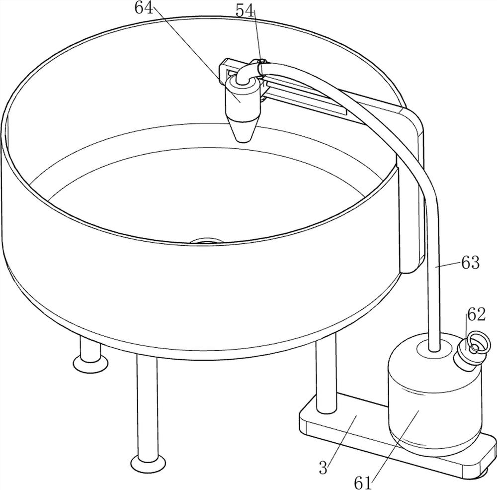
[0027] A gear shot peening device for high-end equipment manufacturing, such as figure 1 As shown, it includes a support column 1, a protective frame 2, a support plate 3, a clamping assembly 4, a sliding assembly 5, and a shot peening assembly 6. The top of the support column 1 is connected with a protective frame 2, and the right side of the support column 1 is fixed There is a support plate 3, and the middle part of the protective frame 2 is provided with a clamping assembly 4 in a rotating manner. The outer wall of the protective frame 2 is equipped with a sliding assembly 5. The sliding assembly 5 is located above the protective frame 2. The sliding assembly 5 and the supporting plate 3 are equipped with spray Pill Component6.

[0028] When the worker needs to shot peen the gear, the worker first needs to pull the clamping assembly 4 to the outside, the clamping assembly 4 is compressed, and when the clamping assembly 4 moves to the outside to a position large enough, the...

Embodiment 2

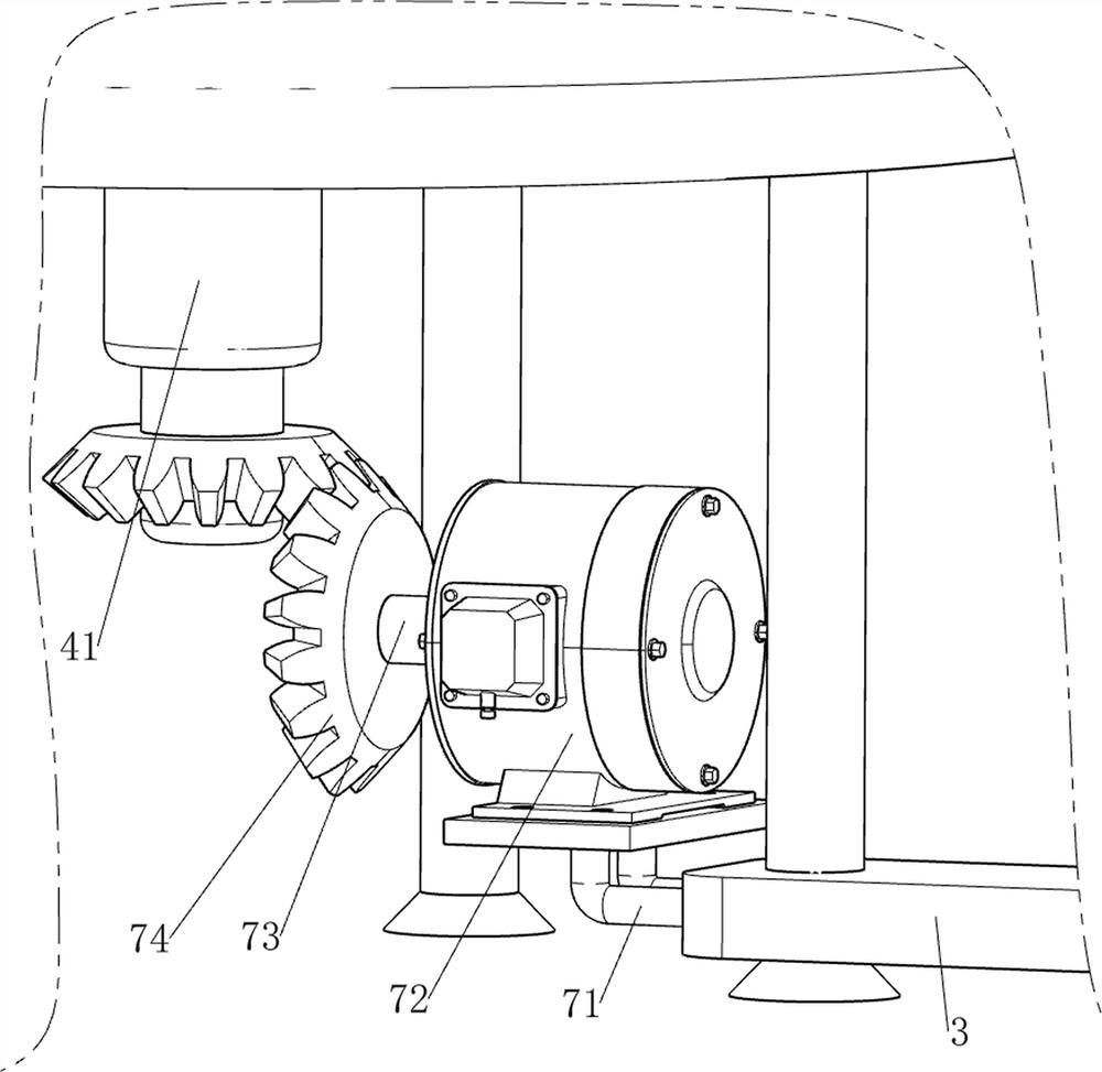
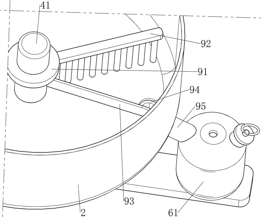
[0030] In a preferred embodiment of the present invention, as figure 2 , image 3 , Figure 4 , Figure 5 , Figure 6 and Figure 7 As shown, the clamping assembly 4 includes a first rotating shaft 41, a turntable 42, a guide rod 44, a first slider 45, a first spring 46 and a clamping rod 47, and the middle part of the protective frame 2 is provided with a first rotating shaft 41 for rotation. , the first rotating shaft 41 is fixedly connected with a turntable 42, and the top of the turntable 42 is spaced with a first chute 43, the number of the first chute 43 is six, and a guide rod 44 is connected between the six first chute 43, The number of guide rods 44 is six, and the six guide rods 44 are all slidably provided with a first slide block 45, and the six guide rods 44 are equipped with a first spring 46, and the two ends of the first spring 46 are respectively connected to the rotating disk 42 and On the first sliders 45 , the tops of the six first sliders 45 are fixe...


PUM


Abstract

The invention relates to a shot blasting device, in particular to a gear shot blasting device for high-end equipment manufacturing. The invention provides the gear shot blasting device for high-end equipment manufacturing, which can perform shot blasting rapidly on a gear, meanwhile, replace shot blasting positions at intervals and recycle fine steel shots rapidly, thereby reducing waste. The gear shot blasting device for high-end equipment manufacturing comprises supporting columns, a protection frame and a supporting plate; and the protection frame is connected among the top ends of the supporting columns, and the supporting plate is fixedly connected to the supporting columns. According to the gear shot blasting device, a clamping assembly is arranged and matched with a sliding assembly, and a gear can be rapidly clamped and loosened according to needs; a shot blasting assembly is matched with the clamping assembly, and fine steel shots can be quickly and uniformly sprayed to the gear according to needs; a rotating assembly is matched with a cleaning assembly, and redundant small steel shots can be quickly swept into the protection frame according to needs; and a recycling assembly is matched with the clamping assembly, fine steel shots can be recycled, and waste of the fine steel shots is reduced.

Description

technical field [0001] The invention relates to a shot blasting device, in particular to a gear shot blasting device used in high-end equipment manufacturing. Background technique [0002] Intensified shot peening is the use of high-speed sprayed fine steel shots to hit the surface of the sprayed workpiece, causing elastic-plastic deformation of the surface material of the workpiece and high residual compressive stress, thereby improving the strength and fatigue resistance of the workpiece surface. For the research on the residual stress and strength improvement of the workpiece, the shot peening process has also been widely used in the civil industry. For the rear axle spiral bevel gears on heavy vehicles, gear manufacturers began to pay attention to and adopt the shot peening process to improve the fatigue resistance process. The efficiency of manual shot peening of gears by workers is low. At the same time, the process of changing the position of gear shot peening at inte...

Claims


Application Information

Patent Timeline
IPC IPC(8): C21D7/06C22F1/00
CPCC21D7/06C22F1/00Y02P10/20
Inventor 雷小平
Owner 雷小平
Learn More