Check patentability & draft patents in minutes with Patsnap Eureka AI!

Thread trimming structure and automatic thread trimming and presser foot lifting integrated zigzag sewing machine

A technology of lifting presser foot and sewing machine, applied in the field of sewing machine, can solve the problems of large moving space of the tool, increasing the cutting range, and unable to cut the suture, etc.

Pending Publication Date: 2021-09-14
浙江龙泰缝纫设备有限公司
View PDF0 Cites 0 Cited by
  • Summary
  • Abstract
  • Description
  • Claims
  • Application Information

AI Technical Summary

Problems solved by technology

[0002] At present, the thread trimming function used in the working process of sewing machines is generally realized by electromagnets, which have the problems of slow response speed and high noise, and the stroke of the electromagnet cannot be changed flexibly, and it is easy to shake during the operation, which is easy Causes the problem of uninterrupted cutting and jamming
[0003] Moreover, in the existing sewing machine products, most of the feed of the thread trimmer is the rotary feed of the knife to cut the thread, and the knife will occupy a large movable space. For the zigzag sewing machine with the needle bar swinging left and right for herringbone sewing, the position range of the suture is limited. Wider, this thread cutting method is prone to continuous cutting or even no sutures, and simply widening the knife to increase the cutting range will make the internal space of the sewing machine too crowded and increase the design cost

Method used


Image

  • Thread trimming structure and automatic thread trimming and presser foot lifting integrated zigzag sewing machine
  • Thread trimming structure and automatic thread trimming and presser foot lifting integrated zigzag sewing machine
  • Thread trimming structure and automatic thread trimming and presser foot lifting integrated zigzag sewing machine

Examples


Embodiment

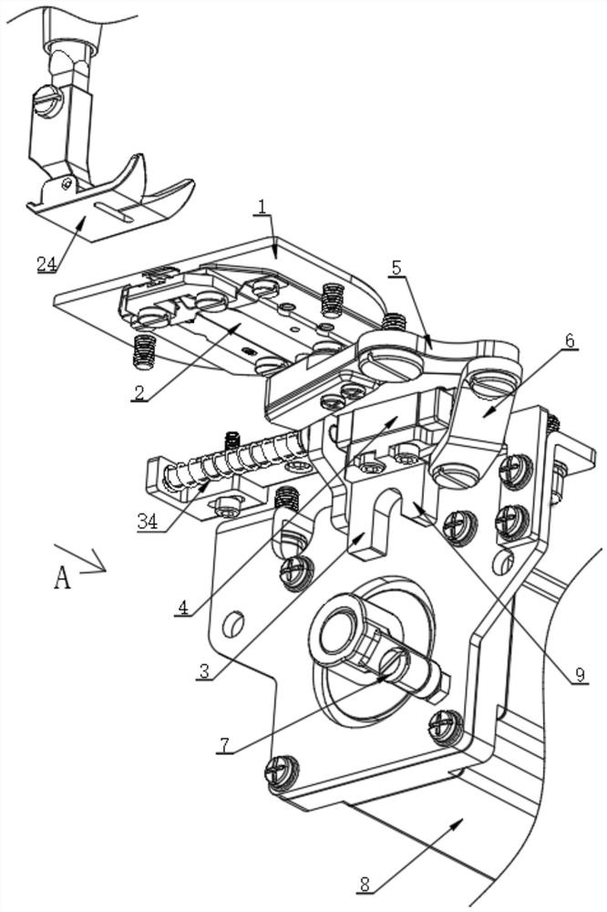
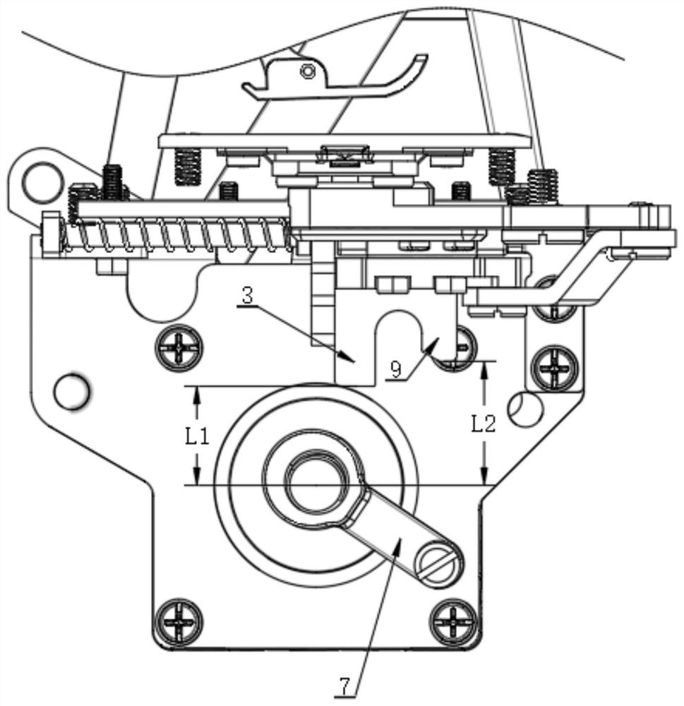
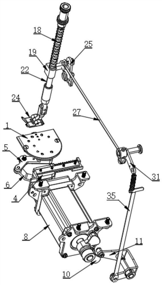
[0025] refer to Figure 1 to Figure 4 As shown, this embodiment provides a thread trimming structure and a zigzag sewing machine with automatic thread trimmer and presser foot lifter, including a thread trimming structure, the thread trimming structure includes a stepping motor assembly 8 and a cam mechanism, and the stepping motor The action of the assembly 8 is controlled by the control box. The cam mechanism is driven by the stepper motor assembly 8 to rotate. The cam mechanism includes a thread trimmer crank 7 and a lift crank 10. The stepper motor assembly 8 is a double output shaft motor, the thread trimming crank 7 and the lifting crank 10 are respectively sleeved on the output shafts on both sides of the stepping motor assembly 8, and the forward and reverse rotation of the stepping motor assembly 8 is controlled by the control box , to control the forward rotation and reverse rotation of the thread trimming crank 7 and the lifting crank 10.

[0026] The thread trimmi...


PUM


Abstract

The invention relates to the technical field of sewing machines, in particular to a thread trimming structure and an automatic thread trimming and presser foot lifting integrated zigzag sewing machine. The thread trimming structure comprises a stepping motor assembly and a cam mechanism; the cam mechanism is driven by the stepping motor assembly to rotate; the cam mechanism is provided with a thread trimming crank; and the thread trimming structure further comprises a needle plate thread trimming assembly, a movable cutter, a thread trimming guide rail assembly and a thread trimming transmission assembly. The thread trimming crank of the cam mechanism is driven by one stepping motor to rotate, a sliding block is driven to move on the thread trimming guide rail assembly, and a thread trimming transmission mechanism drives the movable cutter to advance to complete thread trimming; the structure is simple and stable, the transmission efficiency is high, and the noise is low; and the advancement stroke of the movable cutter is a straight line under the position constraint of the needle plate thread trimming assembly, so that it is ensured that a sewing thread of the zigzag sewing machine can be effectively cut off at any position, and the space occupied by the advancement action is small while the effective cutting range is large.

Description

technical field [0001] The invention relates to the technical field of sewing machines, in particular to a thread trimmer structure and a zigzag sewing machine with an integrated automatic thread trimmer and presser foot lifter. Background technique [0002] At present, the thread trimming function used in the working process of sewing machines is generally realized by electromagnets, which have the problems of slow response speed and high noise, and the stroke of the electromagnet cannot be changed flexibly, and it is easy to shake during the operation, which is easy Causes the problem of continuous cutting and jamming. [0003] Moreover, in the existing sewing machine products, most of the feed of the thread trimmer is the rotary feed of the knife to cut the thread, and the knife will occupy a large movable space. For the zigzag sewing machine with the needle bar swinging left and right for herringbone sewing, the position range of the suture is limited. Wider, this threa...

Claims


Application Information

Patent Timeline
Patent Type & Authority Applications(China)
IPC IPC(8): D05B65/00D05B29/02
CPCD05B65/00D05B29/02
Inventor 朱广运朱龙明卢委丽王健
Owner 浙江龙泰缝纫设备有限公司
Features
  • R&D
  • Intellectual Property
  • Life Sciences
  • Materials
  • Tech Scout
  • Unparalleled Data Quality
  • Higher Quality Content
  • 60% Fewer Hallucinations
Learn More