
Automatic load regulation, operation and protection method for converter saturated steam turbine and motor combined dragging power generation

A technology of load regulation and steam turbine, which is applied in the direction of electromechanical devices, electric components, control generators, etc., and can solve problems such as unreasonable, unstable outlet steam flow, and wrong connection mode of heat accumulator pipelines

Active Publication Date: 2021-09-14
HAINAN JIRUI HAOHAN POWER SYST TECH CO LTD
View PDF5 Cites 2 Cited by
  • Summary
  • Abstract
  • Description
  • Claims
  • Application Information

AI Technical Summary

Problems solved by technology

At present, steam accumulator adjustment generally adopts a regulating system composed of a mechanical check valve and a steam outlet regulating valve, and there are widespread errors or unreasonable situations in the connection mode of the accumulator pipeline; based on the above reasons, the current accumulator It is widely used and has poor heat storage effect and unstable outlet steam flow

Method used


Image

  • Automatic load regulation, operation and protection method for converter saturated steam turbine and motor combined dragging power generation
  • Automatic load regulation, operation and protection method for converter saturated steam turbine and motor combined dragging power generation
  • Automatic load regulation, operation and protection method for converter saturated steam turbine and motor combined dragging power generation

Examples


Embodiment Construction

[0036] Exemplary embodiments of the present invention will be described below with reference to the accompanying drawings. In the interest of clarity and conciseness, not all features of an actual implementation are described in this specification. It should be understood, however, that in developing any such practical embodiment, many implementation-specific decisions must be made in order to achieve the developer's specific goals, such as meeting those constraints related to the system and business, and those Restrictions may vary from implementation to implementation. Furthermore, it should be understood that development work, while potentially complex and time-consuming, would be a routine undertaking for those skilled in the art having the benefit of this disclosure.

[0037] Those skilled in the art can understand that, unless otherwise defined, all terms (including technical and scientific terms) used herein have the same meaning as commonly understood by one of ordina...


PUM


Abstract

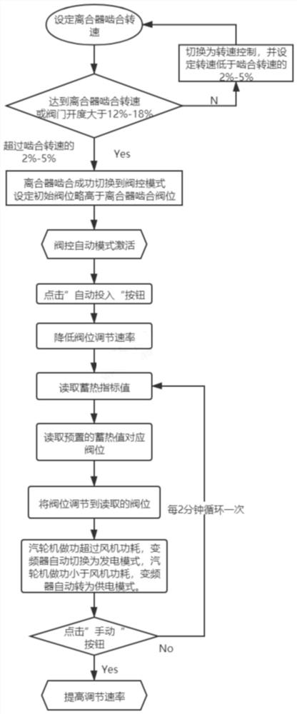
The invention discloses an automatic load regulation, operation and protection method for converter saturated steam turbine and motor combined dragging power generation, and belongs to the technical field of low-pressure saturated steam utilization. Problems that in the prior art, steam is unstable, the energy utilization efficiency is low, and system operation is unstable are solved. The technical key point is that the method comprises: S1, setting a meshing rotating speed; S2, setting a rotating speed control mode; S3, switching to a valve control mode after meshing is successful; S4, activating a valve position automatic mode; S5, entering an automatic mode; S6, reducing a valve position adjusting speed; S7, reading the comprehensive heat storage index value and the preset heat storage value corresponding valve position by a DCS of the dragging steam turbine system; adjusting the valve position to the valve position corresponding to the read heat storage value; when the work of the steam turbine exceeds the fan power consumption, switching the frequency converter automatically to a power generation mode, and when the work is smaller than the fan power consumption, switching the frequency converter to a power supply mode; S8, entering a manual mode; and S9, increasing the adjusting rate. The method is used for controlling the converter saturated steam turbine and motor combined dragging power generation system.

Description

technical field [0001] The invention relates to a control method for combined driving of a saturated steam turbine and a motor for power generation, in particular to an automatic load adjustment, operation and protection method for a combined driving of a saturated steam turbine and a motor for power generation, and belongs to the technical field of low-pressure saturated steam utilization. Background technique [0002] How to efficiently utilize the low-pressure saturated steam produced by the iron and steel production has always been a problem that iron and steel enterprises have been concerned about and hope to solve. In the prior art, the saturated steam recovered in the production of the intermediate converter is sent to the low-pressure steam except part for RH vacuuming. The steam pipe network for domestic steam has not been efficiently utilized. Taking a special steel enterprise as an example, with an annual output of 3 million tons, there are two RH vacuum equipment...

Claims


Application Information

Patent Timeline
IPC IPC(8): F01D17/10F01D19/00F01D21/00F01D15/10H02P9/06H02K7/18
CPCF01D17/10F01D19/00F01D21/00F01D15/10H02P9/06H02K7/1823H02P2101/20F02C9/00F01K13/02F01D15/12F05D2220/31F05D2260/40
Inventor 赵振
Owner HAINAN JIRUI HAOHAN POWER SYST TECH CO LTD
Learn More