Systems and methods for crankcase system diagnostics

A crankcase and air intake system technology, applied in the field of systems and methods for crankcase system diagnosis, capable of solving problems such as reduction

Pending Publication Date: 2021-09-14
FORD GLOBAL TECH LLC
View PDF1 Cites 1 Cited by
  • Summary
  • Abstract
  • Description
  • Claims
  • Application Information

AI Technical Summary

Problems solved by technology

In other words, the pressure sensor may report different pressures from either end of the vent hose, reducing the ability to robustly infer the specific source of degradation associated with the vent hose

Method used


Image

  • Systems and methods for crankcase system diagnostics
  • Systems and methods for crankcase system diagnostics
  • Systems and methods for crankcase system diagnostics

Examples


Embodiment Construction

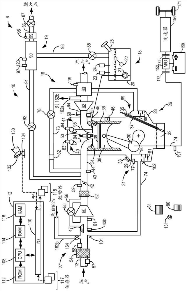
[0020] The following description relates to systems and methods for inferring whether there is degradation associated with a PCV ventilation hose fluidly coupling an engine crankcase to an intake system. therefore, figure 1 An exemplary engine is depicted that includes a PCV system having a ventilation hose fluidly coupling the engine's crankcase to an air intake system. To effectively diagnose the presence or absence of deterioration associated with the ventilation hose, the ventilation hose may be positioned between the intake system and the crankcase pressure (CKCP) sensor, rather than, for example, at a location on the ventilation hose Includes CKCP sensor. The oil-air separator may be included in the crankcase of the engine and may include one or more sealing baffles that may respond to pressure differentials (eg, between the ventilation hose and the crankcase) Respond so that the oil separator effectively seals the ventilation hose from the crankcase when there is no p...


PUM


Abstract

Provided are systems and methods for crankcase system diagnostics. Methods and systems are provided for assessing a state of a vent hose that fluidically couples a crankcase of an engine to an engine air intake system. In one example, a method may include sealing the crankcase from the vent hose, initiating cranking of the engine, monitoring a series of pressure pulsations during a monitoring window duration via a pressure sensor positioned between a crankcase oil separator and the vent hose, and indicating a presence of degradation associated with the vent hose based on the series of pressure pulsations and the monitoring window duration. In this way, diagnosis of a state of the vent hose may be reliably assessed without crankcase pressures confounding pressure measurements as recorded via the pressure sensor.

Description

technical field [0001] The present specification generally relates to methods and systems for inferring whether a ventilation hose fluidly coupling a crankcase to an intake system of an engine is deteriorating or functioning as intended or desired. Background technique [0002] During the power stroke of the piston of an engine cylinder, a portion of the gases combusted within the cylinder may escape through rings that form a seal around the piston base in a process known as blow-by. The escaping gases can build up in the crankcase, causing pressure build-up that can degrade the oil stored in the crankcase that lubricates the movement of the pistons. The engine may include a crankcase ventilation system to exhaust gases out of the crankcase and into the engine intake manifold to provide continuous exhaust from the interior of the crankcase in order to reduce degradation of various engine components in the crankcase. The crankcase ventilation system may include a positive cr...

Claims


Application Information

Patent Timeline
Patent Type & Authority Applications(China)
IPC IPC(8): F01M1/18F01M13/00F01M13/04F02M25/06
CPCF01M1/18F01M13/00F01M13/04F02M25/06B01D45/08F01M13/0011F01M2013/0083F01M2250/64F02M35/10222F02M35/1038F02M35/09Y02T10/12F01M11/03B60K6/28B60K6/26B60K6/24B60Q9/00
Inventor 罗伯特·雷·詹特斯M·卡彭特M·S·斯威皮亚当·约瑟夫·克拉奇
Owner FORD GLOBAL TECH LLC
Why Eureka
Try Eureka