
Exhaust device for negative pressure isolation ward

A technology of negative pressure isolation and exhaust device, which is applied in the field of air purification in negative pressure isolation wards, can solve the problems of poor recovery of patients and high risk of infection of medical staff.

Pending Publication Date: 2021-09-14
CHINA FIRST METALLURGICAL GROUP
View PDF2 Cites 1 Cited by
  • Summary
  • Abstract
  • Description
  • Claims
  • Application Information

AI Technical Summary

Problems solved by technology

Due to urgent use requirements and convenient and fast installation, the location of ventilation ducts in many negative pressure wards during the construction process cannot fully serve the convenience of air diffusion and rapid convection discharge, but more consideration should be given to how to install them more quickly Integral piping system, which brings about a series of problems in the process of gas replacement in the room
If the infectious disease pollution gas in the ward cannot be discharged in a reasonable and timely manner, it will be detrimental to the recovery of the patient, and even increase the risk of infection for the medical staff, and there are certain hidden dangers

Method used


Image

  • Exhaust device for negative pressure isolation ward
  • Exhaust device for negative pressure isolation ward
  • Exhaust device for negative pressure isolation ward

Examples


Embodiment Construction

[0026] The present invention will be described in detail below in conjunction with specific embodiments and examples, and the advantages and various effects of the present invention will be presented more clearly. Those skilled in the art should understand that these specific implementations and examples are used to illustrate the present invention, not to limit the present invention.

[0027] Throughout the specification, unless otherwise specified, terms used herein should be understood as commonly used in the art. Therefore, unless otherwise defined, all technical and scientific terms used herein have the same meaning as commonly understood by one of ordinary skill in the art to which this invention belongs. In case of conflict, this specification shall take precedence.

[0028] It should be noted that when an element is referred to as being "fixed" or "disposed on" another element, it may be directly disposed on another element or indirectly disposed on another element; w...


PUM


Abstract

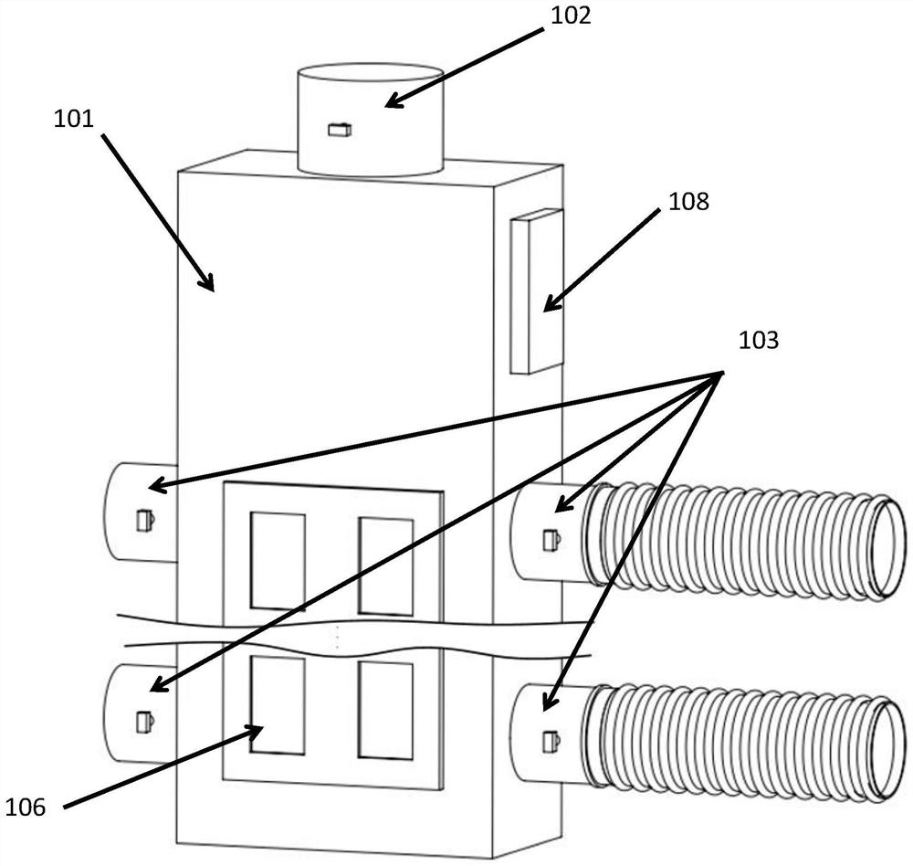
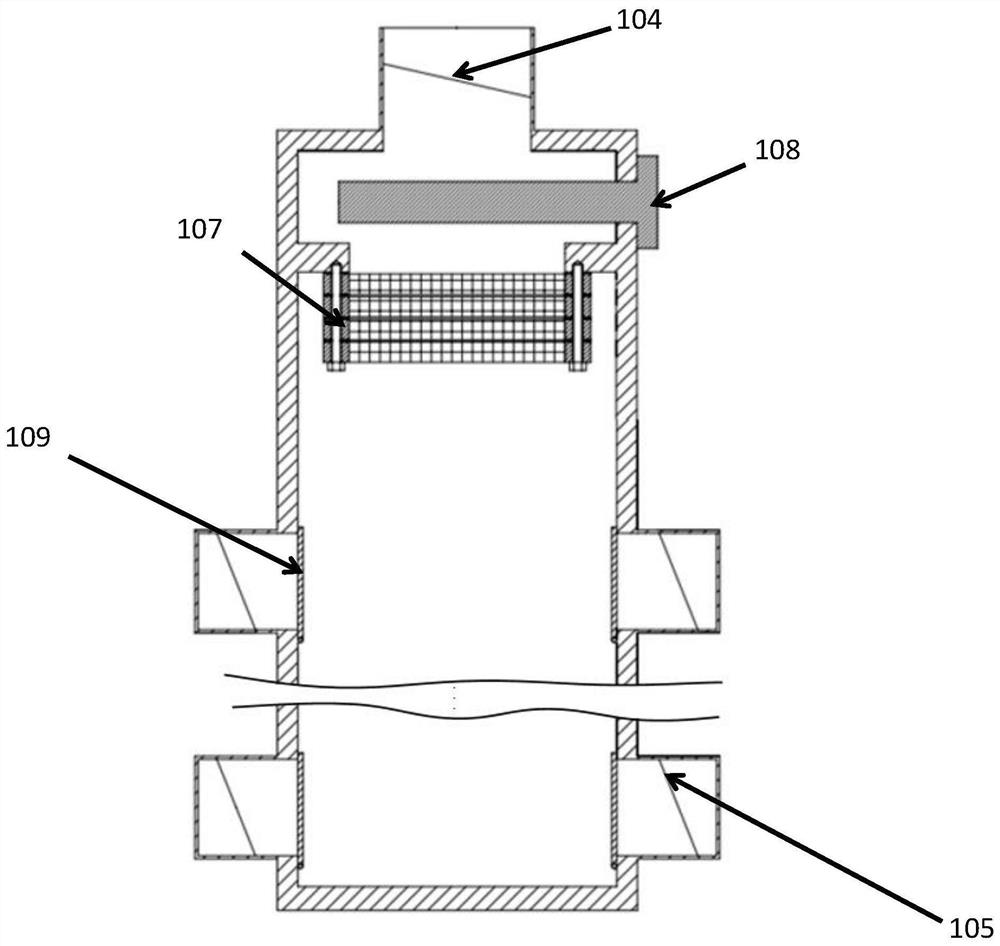
The invention discloses an exhaust device for a negative pressure isolation ward. The exhaust device comprises an exhaust body and a plurality of telescopic corrugated pipes. The exhaust body comprises a box, an air outlet, a plurality of air inlets, an air outlet valve and air inlet valves, wherein the air outlet and the air inlets are formed in the box, the air outlet valve is arranged on the air outlet, the air inlet valves are arranged on the air inlets, and the air outlet is used for being communicated with an exhaust pipeline in the negative pressure isolation ward. One end of each telescopic corrugated pipe is communicated with the corresponding air inlet, and the other end of each telescopic corrugated pipe is used for being communicated with the portion, needing air exhaust, of the negative pressure isolation ward. According to the exhaust device, the exhaust body is communicated with the building exhaust pipeline in the negative pressure isolation ward, the air inlets of the box are connected with the external telescopic corrugated pipe air exhaust pipelines, and the air outlet valve and the air inlet valves are used for controlling opening and closing of the pipelines, so that the purposes of guiding the flow direction of air in the ward and increasing the air change speed by changing the positions of exhaust openings are achieved. The problem that according to an existing exhaust device on the market, the positions of air change ventilation openings cannot be scientifically and reasonably set is solved.

Description

technical field [0001] The invention relates to the technical field of air purification in a negative pressure isolation ward, in particular to an exhaust device for a negative pressure isolation ward. Background technique [0002] Recently, with the outbreak of the pneumonia epidemic, hospitals in various places have increased their demand for the construction of negative pressure wards that can control infectious diseases, and many such wards have been quickly completed and put into use. Due to urgent use requirements and convenient and fast installation, the location of ventilation ducts in many negative pressure wards during the construction process cannot fully serve the convenience of air diffusion and rapid convection discharge, but more consideration should be given to how to install them more quickly The overall piping system, which brings a series of problems in the process of gas replacement in the room. If the infectious disease pollution gas in the ward cannot ...

Claims


Application Information

Patent Timeline
IPC IPC(8): F24F7/06F24F7/003F24F8/108F24F8/158F24F8/20F24F8/30F24F13/02F24F13/08F24F13/28
CPCF24F7/06F24F7/003F24F8/108F24F8/158F24F8/20F24F8/30F24F13/02F24F13/08F24F13/28
Inventor 呙于平喻秋龙龙明李娜潘艳桥刘志豪汪卓
Owner CHINA FIRST METALLURGICAL GROUP
Learn More