CT slip ring electric brush and forming method thereof

A technology for brush holders and slip rings, which can be used in the manufacture of slip rings, circuits, collectors, etc., and can solve the problem of high cost

Pending Publication Date: 2021-09-14
杭州全盛机电科技有限公司
View PDF6 Cites 1 Cited by
  • Summary
  • Abstract
  • Description
  • Claims
  • Application Information

AI Technical Summary

Problems solved by technology

At present, thick copper clad laminates are mostly used as the carrier in the market, so the cost is relatively high

Method used


Image

  • CT slip ring electric brush and forming method thereof
  • CT slip ring electric brush and forming method thereof
  • CT slip ring electric brush and forming method thereof

Examples


Embodiment 1

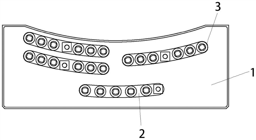
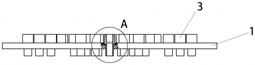
[0034] figure 1 , 2 , 3, a CT slip ring brush holder, including a frame body 1 and a brush holder 3, the frame body is cuboid, the frame body is provided with conductive channels 2, the conductive channels are provided with 4, and each conductive The shape of the channel is adapted to the shape of the conductive slip ring on the CT slip ring. The conductive channel is opened on one side of the frame body. The conductive channel is actually a groove opened on the side of the frame body, and the conductor is installed and placed in the groove.

[0035] The conductive channel is provided with a brush holder installation hole, the installation hole is set through the frame body, and each conductive channel is provided with 5 or 6 brush holder installation holes, wherein the brush holder is installed in each brush holder installation hole.

[0036] Among them such as figure 1 As shown, the positions of the 4 conductive channels are adapted to the shape of the conductive slip ring...

Embodiment 2

[0038] Embodiment 2: A method for forming a CT slip ring brush holder, comprising the following steps:

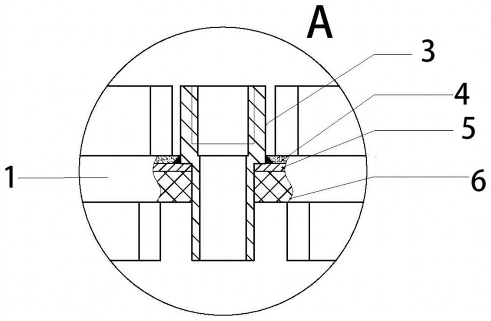
[0039] (1) Cut the 8mm thick phenolic resin plate and the 2mm thick H59 copper plate into cuboids with equal length and width. (2) Apply 3M DP760 epoxy resin evenly on one side of the phenolic board, (3) Put the coated phenolic board and the copper board in a vacuum bag at the same time, and slide the copper board to the position aligned with the phenolic board while vacuuming And press the copper plate to distribute the epoxy resin evenly, take out the parts and wait for the epoxy resin to cure. (4) Then mill the required conductive channel in the installation hole of the brush holder. Air blowing is used for cooling during milling and cutting fluid cannot be used. (5) Insert the brush holder into the hole, use induction heating equipment to solder the brush holder and the copper plate, and control the welding temperature at 245±5°C by controlling the power and heating ti...


PUM

PropertyMeasurementUnit
Thicknessaaaaaaaaaa

Abstract

The invention discloses a CT slip ring electric brush carrier and a forming method thereof, the CT slip ring electric brush carrier comprises a CT slip ring electric brush carrier, the CT slip ring electric brush carrier comprises a carrier body and a brush holder, the carrier body is provided with a conductive channel and a brush holder mounting hole for mounting and placing the brush holder, the carrier body is composed of a phenolic resin plate and a copper plate arranged on the phenolic resin plate, and a tawny semitransparent epoxy resin layer is also arranged on the outer surface of the copper plate. According to the invention, the phenolic resin plate and the copper plate are adhered to each other to replace an existing thick copper-clad plate, so that the use of copper is reduced, and the cost is reduced.

Description

technical field [0001] The invention relates to the technical field of CT slip rings, in particular to a CT slip ring brush holder and its forming method. Background technique [0002] Large disc slip rings are used in applications where space in the height direction of the slip ring is limited. For example in the medical device, measuring, testing, printing and textile industries. At present, CT slip rings in CT machines generally adopt such large disc slip rings. [0003] Wherein, when the CT machine rotates, its upper parts need high-power electric energy of more than 80kW. Therefore, the CT slip ring needs to be able to pass a large operating current, generally a 120A channel. Limited by the size of the machine, each channel of the CT slip ring power ring requires 6 to 10 carbon brushes connected in parallel as current pickup components. [0004] Among them, the brush needs to be fixed with a brush holder. At present, thick copper clad laminates are mostly used as t...

Claims


Application Information

Patent Timeline
IPC IPC(8): H01R39/38H01R43/12H01R43/10
CPCH01R39/38H01R43/12H01R43/10
Inventor 李冰刘益清李琪
Owner 杭州全盛机电科技有限公司
Why Eureka
Try Eureka