Soil taking and hole forming device based on reverse rotation and hole forming method of soil taking and hole forming device
A technology of forming holes and installing plates, which is applied in the directions of planting methods, excavation/covering trenches, applications, etc., which can solve the problem of poor forward speed, difficulty in transplanting pot seedlings to meet agronomic requirements, and ventilation between soil particles around the holes issues such as sexual decline
- Summary
- Abstract
- Description
- Claims
- Application Information
AI Technical Summary
Problems solved by technology
Method used
Image
Examples
Embodiment 1
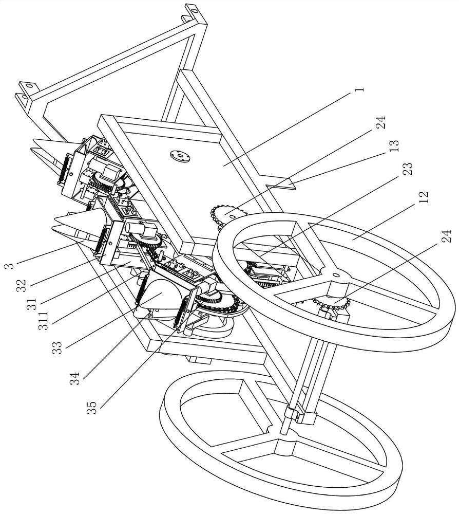
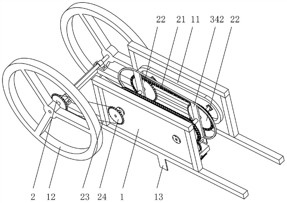
[0036] Such as figure 1 with figure 2 As shown, the soil-taking and caving-forming device based on reverse rotation in this embodiment includes a frame 1, a transmission mechanism 2, and a soil-taking and caving-forming mechanism 3. The mechanism 3 travels; the vertical plane parallel to the walking direction in the frame 1 is provided with a rotary closed track 11, the soil-taking and caving mechanism 3 is slid on the track 11, and the transmission mechanism 2 is driven by the walking motion of the frame 1. The soil-taking and caving mechanism 3 slides around the track 11; the rail 11 is provided with a first rail section parallel to the ground, and the sliding direction of the soil-taking and caving mechanism 3 on the first rail section is opposite to the walking direction of the frame 1 and Make holes in the ground.
[0037]In the hole making process, the running direction of the soil-taking and forming-caving mechanism 3 on the track 11 is opposite to the walking direct...
Embodiment 2
[0064] The present embodiment provides the operating cycle of the soil-taking and caving-forming mechanism 3:
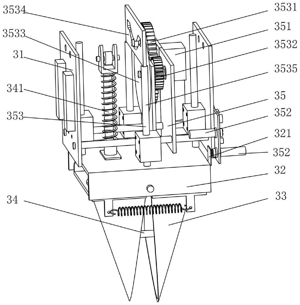
[0065] When the soil-taking and caving-forming mechanism 3 performs rotary motion along the track 11 and has not yet entered the caving stage, the photoelectric switch 352 is not triggered, the motor 351 is in a non-working state, and the rotating disk 3533, chute plate 3534, push rod 341, cam 342 and Parts such as the soil-borrowing sheet are in a relatively static state. At this time, the roller shaft of the rotating disk 3533 is in the symmetrical center position of the chute plate 3534, and the soil-taking piece 33 and the push rod 341 are all at the beginning position of the soil-entry stage of the cam 342. Contact with the outer contour of the cam 342 all the time, and the soil-taking piece 33 is in an open posture.
[0066] When the motor 351 rotates, it drives the first gear 3531 and the second gear 3532 meshed with it to rotate, and the second gear 3532 dri...
PUM
 Abstract
Description
Claims
Application Information
 - R&D
- Intellectual Property
- Life Sciences
- Materials
- Tech Scout
- Unparalleled Data Quality
- Higher Quality Content
- 60% Fewer Hallucinations
Browse by: Latest US Patents, China's latest patents, Technical Efficacy Thesaurus, Application Domain, Technology Topic, Popular Technical Reports.
© 2025 PatSnap. All rights reserved.Legal|Privacy policy|Modern Slavery Act Transparency Statement|Sitemap|About US| Contact US: help@patsnap.com


