Multi-directional flue gas cooling element
A component and flue gas technology, applied in tobacco, cigar manufacturing, application, etc., can solve the problem of weak cooling effect, achieve strong cooling effect, improve cooling effect, and enrich the effect of cooling direction
- Summary
- Abstract
- Description
- Claims
- Application Information
AI Technical Summary
Problems solved by technology
Method used
Image

Examples
Embodiment 1
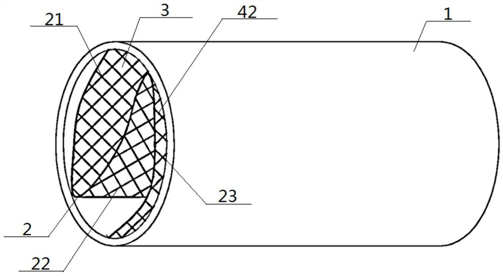
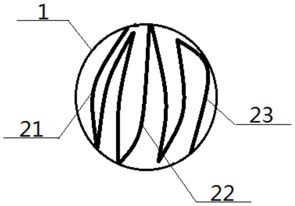
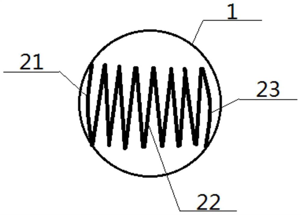
[0073] A multi-directional flue gas cooling element, comprising an outer wrapping cylinder 1 and an inner filling body 2 arranged inside, the outer wrapping barrel 1 is a hollow cylindrical structure; the inner filling body 2 includes a beginning net connected as a whole 21. An intermediate network 22 and a terminal network 23, the number of the start-end network 21 and the terminal network 23 is one, the number of the intermediate network 22 is at least one, and the start-end network 21, the intermediate network 22, and the terminal network 23 are all It is woven from a filament 42, and a through hole 41 is woven to form a ventilation hole 3; see Figure 14 , the top edge or bottom edge of the start net 21 is connected with the top edge or bottom edge of an intermediate net 22 adjacent to the start net 21, and the top edge or bottom edge of the end net 23 is connected with the end net 23 The top edge or bottom edge of an adjacent intermediate network 22 is connected; there is...
Embodiment 2
[0075] Basic content is the same as embodiment 1, the difference is:
[0076] see Figure 4 , Figure 5 , Image 6 and Figure 7 , the filaments 42 include warp threads 31 and weft threads 32 , the number of the warp threads 31 and the weft threads 32 are multiple, and the warp threads 31 and the weft threads 32 are interwoven to form the ventilation holes 3 . Preferably, the filament 42 also includes a close-knit thread 33, and the number of the close-knit thread 33 is at least one; the extension direction of the close-knit thread 33 is radial or latitudinal or has both radial and weft directions; The ventilation holes 3 include basic holes 34 and fine-tuned holes 35 , the warp threads 31 and weft threads 32 interweave to form the basic holes 34 , and the densely-tuned threads 33 interweave with the warp threads 31 and weft threads 32 to form the finely-tuned holes 35 .
Embodiment 3
[0078] Basic content is the same as embodiment 2, the difference is:
[0079] The starting network 21, the intermediate network 22, and the terminal network 23 include any one or any combination of the following layout structures;
[0080] Single structure 36: the number of densely tuned threads 33 is one, arranged on the side of a single weft thread 32, and parallel to the single weft thread 32;
[0081] Double structure 37: the number of densely tuned threads 33 is two, which are respectively arranged on both sides of a single weft thread 32, and are all parallel to the single weft thread 32;
[0082] Multi-even structure 38 : the number of finely tuned threads 33 is an even number greater than two, and the same number is arranged on both sides of a single weft thread 32 , and they are all parallel to the single weft thread 32 .
PUM
 Abstract
Description
Claims
Application Information
 - R&D
- Intellectual Property
- Life Sciences
- Materials
- Tech Scout
- Unparalleled Data Quality
- Higher Quality Content
- 60% Fewer Hallucinations
Browse by: Latest US Patents, China's latest patents, Technical Efficacy Thesaurus, Application Domain, Technology Topic, Popular Technical Reports.
© 2025 PatSnap. All rights reserved.Legal|Privacy policy|Modern Slavery Act Transparency Statement|Sitemap|About US| Contact US: help@patsnap.com