Efficient scalpel sterilization device for neurology department

A sterilizing device and neurology technology, applied in water supply devices, sanitary equipment for toilets, heating, etc., can solve the problems of inconvenient feeding and retrieving materials, long time consumption of high temperature sterilization and ozone sterilization, etc., and achieve shortening The effect of long sterilization time and convenient feeding and retrieving

Pending Publication Date: 2021-09-17
余志昊
View PDF9 Cites 3 Cited by
  • Summary
  • Abstract
  • Description
  • Claims
  • Application Information

AI Technical Summary

Problems solved by technology

[0005] In order to overcome the shortcomings of the prior art that high temperature sterilization and ozone sterilization take a long time and are not convenient for feeding and retrieving materials, the technical problem is to provide a method that shortens the time of high temperature and ozone sterilization and is convenient for feeding and retrieving High-efficiency sterilization device for scalpels in neurology

Method used


Image

  • Efficient scalpel sterilization device for neurology department
  • Efficient scalpel sterilization device for neurology department
  • Efficient scalpel sterilization device for neurology department

Examples


Embodiment 1

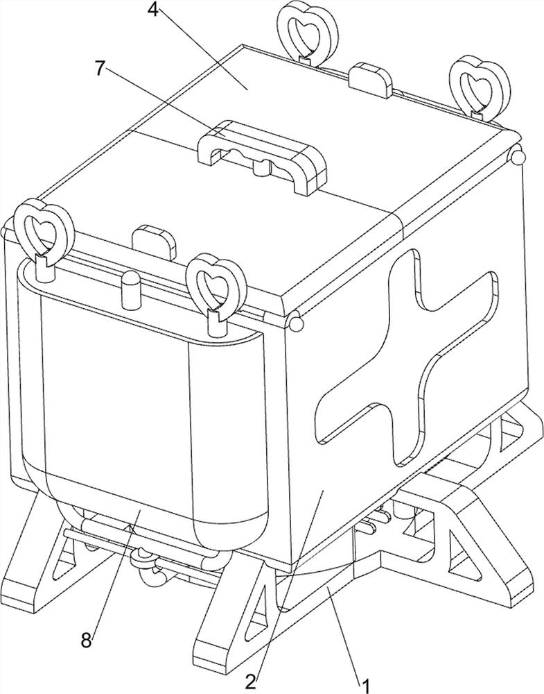
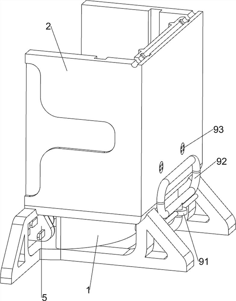
[0030] A high-efficiency sterilization device for scalpels in neurology, such as figure 1 , figure 2 , image 3 , Figure 4 and Figure 5 As shown, it includes a support frame 1, a placement frame 2, a heating tube 3, a placement mechanism 4 and a sterilization mechanism 5. The top of the support frame 1 is provided with a placement frame 2, and the lower part of the placement frame 2 is provided with a heating tube 3. A placing mechanism 4 is provided, and a sterilizing mechanism 5 is provided on the top of the support frame 1, and the sterilizing mechanism 5 is located at the lower part of the placing frame 2.

[0031] Placement mechanism 4 includes cover plate 41, limit plate 42, pull ring 43, block 44 and first spring 45, and placement frame 2 top left and right symmetrical rotations are provided with cover plate 41, placement frame 2 insides are provided with up and down symmetrical sliding type. Limit plate 42, limit plate 42 tops are all symmetrically provided with...

Embodiment 2

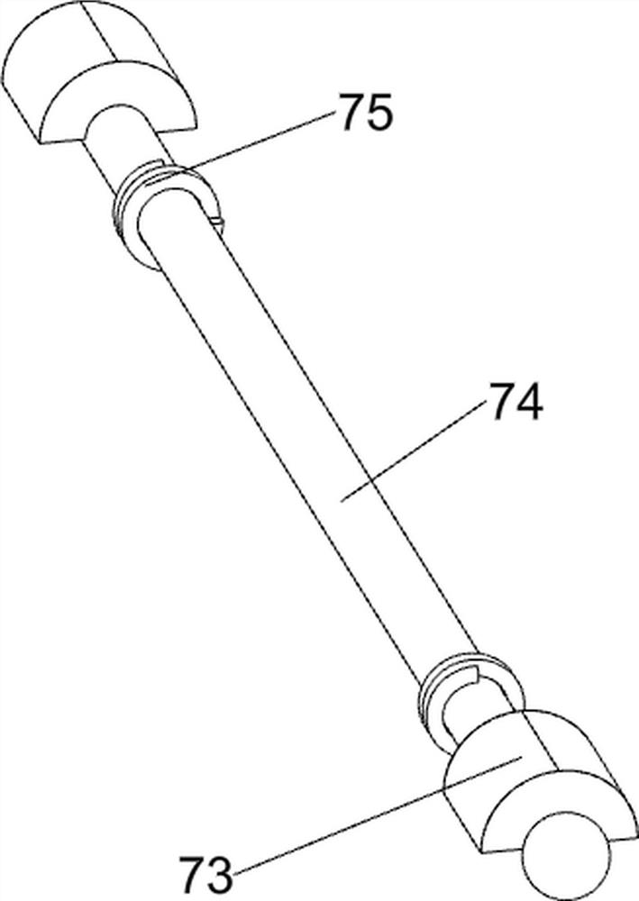
[0035] On the basis of Example 1, such as Figure 6 , Figure 7 , Figure 8 , Figure 9 and Figure 10 As shown, a lifting assembly 6 is also included. The lifting assembly 6 includes a baffle plate 61, a first guide rod 62, a second spring 63, a pull rod 64, a limit block 65 and a connecting rod 66, and the lower side of the placement frame 2 is left and right symmetrical. A first guide rod 62 is provided, and a baffle plate 61 is slidably arranged between the first guide rods 62. The baffle plate 61 cooperates with the limit plate 42, and a second spring 63 is arranged between the baffle plate 61 and the first guide rod 62. , the second springs 63 are all set on the first guide rod 62, and the front and rear sides of the baffle plate 61 are symmetrically provided with pull rods 64, and the pull rods 64 are all slidably connected with the inner wall of the placement frame 2, and the middle part of the inner wall of the placement frame 2 is symmetrically provided with two ...


PUM


Abstract

The invention relates to a sterilization device, in particular to an efficient scalpel sterilization device for the neurology department. The technical problem to be solved is to provide the efficient scalpel sterilization device for the neurology department, which shortens the high-temperature and ozone sterilization time and is convenient for material feeding and taking. According to the technical scheme, the efficient scalpel sterilization device for the neurology department comprises a supporting frame, a containing frame, a heating pipe, a containing mechanism and a sterilization mechanism, wherein the containing frame is arranged at the top portion of the supporting frame, the heating pipe is arranged at the lower portion of the containing frame, the containing mechanism is arranged on the containing frame, and the sterilization mechanism is arranged at the top portion of the supporting frame and located on the lower portion of the containing frame. According to the invention, the effects of shortening the high-temperature and ozone sterilization time and facilitating feeding and taking are achieved.

Description

technical field [0001] The invention relates to a sterilizing device, in particular to a high-efficiency sterilizing device for a scalpel used in neurology. Background technique [0002] A scalpel is composed of a blade and a handle. According to the connection form of the blade and the handle, it can be divided into two types: a detachable scalpel and a fixed scalpel. The scalpel is generally used for cutting human or animal tissues. The cutting tool is also an indispensable and important surgical tool in surgery. [0003] However, in the process of sterilizing the scalpel, high temperature sterilization and ozone sterilization in the prior art take a long time, resulting in low work efficiency of medical staff, and after high temperature, the temperature inside the device is high, and the scalpel is hot , making it inconvenient for medical staff to feed and take out materials. [0004] In view of the above-mentioned problems in the prior art, it is necessary to design a ...

Claims


Application Information

Patent Timeline
Patent Type & Authority Applications(China)
IPC IPC(8): A61L2/04A61L2/20A61L2/26A61L101/10
CPCA61L2/04A61L2/202A61L2/26A61L2202/11A61L2202/24
Inventor 余志昊
Owner 余志昊
Why Eureka
Try Eureka