Rotary cutting tool for wire cutting of part

A rotary cutting and wire cutting technology, which is applied in the field of parts cutting, can solve the problems such as the peripheral processing of circular shaft-shaped parts, and achieve the effects of improving efficiency, expanding the processing range, and simplifying manufacturing

Pending Publication Date: 2021-09-17
CHONGQING HUAYU ELECTRIC GRP
View PDF0 Cites 1 Cited by
  • Summary
  • Abstract
  • Description
  • Claims
  • Application Information

AI Technical Summary

Problems solved by technology

[0005] In view of the above-mentioned deficiencies in the prior art, the purpose of the present invention is to provide a rotary cutting tool for wire-cut parts, which solves the problem that the existing wire-cut machine cannot process the periphery of the circular shaft-shaped parts

Method used


Image

  • Rotary cutting tool for wire cutting of part
  • Rotary cutting tool for wire cutting of part
  • Rotary cutting tool for wire cutting of part

Examples


Embodiment

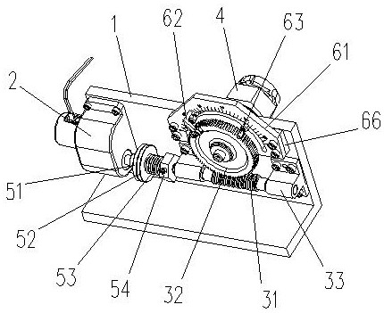
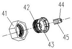
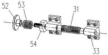
[0026] Example: see Figure 1-Figure 4 , a rotary cutting tool for wire cutting parts, including a fixed support 1, a driving motor 2, a transmission mechanism and a workpiece gripper 4. The fixed support 1 has a bearing plate. In practice, the fixed support 1 also includes a base plate, on which there are installation holes for connecting with the machine tool of the cutting machine. The bearing plate is installed on the bottom plate, and the entire fixed support 1 is L-shaped or T-shaped. The driving motor 2 is fixedly installed on one side of the bearing plate, and the transmission mechanism and the driving motor 2 are located on the same side of the bearing plate, and are connected with the driving motor 2 through a clutch mechanism, which includes a worm 31, a worm gear 32 and a worm gear 32 shaft; The two ends of the worm 31 are respectively connected to the bearing plate through a worm seat 33, and can freely rotate around its axis; the worm wheel 32 is fixedly connect...

Embodiment approach

[0027]During specific implementation, the clutch mechanism includes an active friction disc 51 and a driven friction disc 52, the active friction disc 51 is connected with the output shaft of the drive motor 2, the driven friction disc 52 is connected with the end of the worm 31 close to the drive motor 2, and the active friction disc The disk 51 and the driven friction disk 52 are in close contact with each other, and the driven friction disk 51 can drive the driven friction disk 52 to rotate and drive the worm 31 to rotate. With this solution, the driving motor 2 drives the active friction disc 51 to rotate, and the active friction disc 51 and the driven friction disc 52 rub against each other to transmit torque, so that the driven friction disc 52 rotates, and then drives the worm 31 to rotate; the structure is simple and easy to assemble and adjust. As an embodiment, the clutch mechanism also includes a compression spring 53 and an adjustment nut 54, the adjustment nut 54 i...


PUM


Abstract

The invention discloses a rotary cutting tool for wire cutting of a part. The rotary cutting tool comprises a fixed support, a driving motor, a transmission mechanism and a workpiece clamping jaw, wherein the fixed support is provided with a bearing plate; the driving motor is fixedly installed at one side of the bearing plate; the transmission mechanism is connected with the driving motor through a clutch mechanism and comprises a worm, a worm wheel and a worm wheel shaft; the worm is fixedly connected with the bearing plate through a worm seat; the worm wheel shaft is rotatably connected with the bearing plate, one end of the worm wheel shaft is fixedly connected with the worm wheel, and the other end of the worm wheel shaft penetrates through the bearing plate to be fixedly connected with the workpiece clamping jaw; and the worm is meshed with the worm wheel. The rotary cutting tool is installed on a wire cutting machine tool, the worm wheel shaft is parallel to or perpendicular to the X axis and the Y axis of the wire cutting machine, and then a machined part is installed on a chuck; and through forward rotation, reverse rotation and stopping of the driving motor, the machined part is finally driven to rotate, and rotary cutting of the machined part by the wire cutting machine is achieved.

Description

technical field [0001] The invention relates to the technical field of part cutting, in particular to a rotary cutting tool for wire-cut parts. Background technique [0002] In the manufacturing process of machined parts, some parts have narrow slots and clear corners around them. When traditional turning and milling cannot process them, they need to be processed by EDM and wire cutting. [0003] The wire cutting machine uses the moving wire as the tool electrode, and passes a pulse current between the wire and the workpiece, and uses the corrosion effect of the pulse discharge to cut the workpiece. [0004] The current wire-cutting machine tools (slow wire, medium wire, etc.) are mutually perpendicular two-axis (X, Y) control, wire-feeding EDM processing. However, for the fan-shaped narrow slots on the periphery of the machining round shaft parts, such as figure 1 , The outer frame of the connector part cannot be directly processed by wire cutting. Contents of the inven...

Claims


Application Information

Patent Timeline
Patent Type & Authority Applications(China)
IPC IPC(8): B23H11/00B23H7/02
CPCB23H11/003B23H7/02
Inventor 张毅杨波肖宇宽黎刚李店陈伟
Owner CHONGQING HUAYU ELECTRIC GRP
Why Eureka
Try Eureka