Plate chamfering device for numerical-control machine tool

A technology of CNC machine tools and chamfering devices, which is applied in positioning devices, metal processing mechanical parts, clamping and other directions, can solve the problems of increasing the workload of staff and reducing the working efficiency of the device, and achieves increasing labor costs, reducing labor, The effect of increasing the efficiency of chamfering

Inactive Publication Date: 2021-09-17
孟华伟
View PDF0 Cites 0 Cited by
  • Summary
  • Abstract
  • Description
  • Claims
  • Application Information

AI Technical Summary

Problems solved by technology

[0003] When the CNC machine tool is used, the plate can be chamfered to prevent the barbs after processing from affecting the user. At the same time, it is also necessary to chamfer the through hole on the plate. Both ends of the through hole need to be chamfered. At present, when the existing plate chamfering device for CNC machine tools is used to chamfer the through hole on the plate, only one end of the through hole can be chamfered at a time, and then the plate needs to be turned over to perform secondary chamfering. This way of working will greatly reduce the working efficiency of the device and increase the workload of the staff. Therefore, it is urgent to design a plate chamfering device for CNC machine tools to solve the above problems

Method used


Image

  • Plate chamfering device for numerical-control machine tool
  • Plate chamfering device for numerical-control machine tool
  • Plate chamfering device for numerical-control machine tool

Examples


Embodiment 1

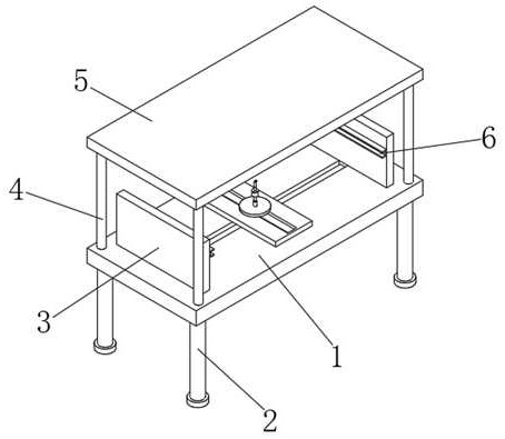
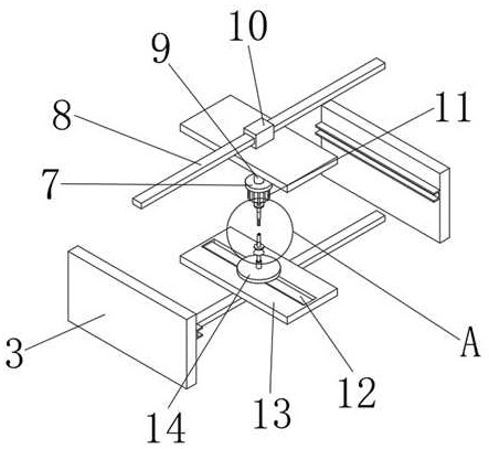
[0029] refer to Figure 1-6, a plate chamfering device for a CNC machine tool, comprising a workbench 1, the four corners of the top outer wall of the workbench 1 are connected with support rods 4 by bolts, and the top outer wall of the support rod 4 is connected with the same top plate 5 by bolts, and the work The four corners of the bottom outer wall of table 1 are connected with support legs 2 by bolts, and the bottom outer walls of support legs 2 are connected with anti-skid pads by bolts, and the bottom outer wall of top plate 5 and the top outer wall of workbench 1 are fixedly equipped with position adjustment mechanisms , and the bottom of the position adjustment mechanism at the top is provided with a first electric push rod 9, the bottom outer wall of the first electric push rod 9 is connected with a motor mounting plate 7 by bolts, and the bottom outer wall of the motor mounting plate 7 is connected with a rotating shaft by bolts The motor 11, the top outer wall of t...

Embodiment 2

[0035] refer to Figure 1-7 , a plate chamfering device for a CNC machine tool, the position adjustment mechanism at the bottom is replaced by a first slide rail 32, the outer wall of the first slide rail 32 is slidably provided with a fourth slider 31, and the outer wall of the fourth slider 31 The sliding plate 30 is connected by bolts, the outer wall of the sliding plate 30 is fixedly provided with the second sliding rail 29, and the outer wall of the second sliding rail 29 is slidably provided with the fifth slider, and the outer wall of the fifth sliding block is connected with the second sliding block by bolts. The electric push rod mounting plate, and two connecting frames 28 are connected by bolts between the outer peripheral wall of the second electric push rod mounting plate and the peripheral outer wall of the first electric push rod mounting plate 14 .

[0036] Working principle: Before grinding, install the plate on the clamping key 6, drive the first slider 10 to...


PUM


Abstract

The invention belongs to the technical field of numerical-control machine tools, particularly relates to a plate chamfering device for a numerical-control machine tool, and provides the following scheme now to solve the technical problem that the two ends of a through hole cannot be chamfered at the same time. The plate chamfering device comprises a workbench, supporting rods are fixedly connected to the four corners of the out wall of the top of the workbench, the outer walls of the tops of the supporting rods are fixedly connected with the same top plate, supporting legs are fixedly connected to the four corners of the outer wall of the bottom of the workbench, and the outer walls of the bottoms of the supporting legs are fixedly connected with non-slip mats. When a through hole of a plate is chamfered, a first electric push rod drives a chamfering grinding head to move downwards, so that an inserting rod is driven to move downwards, a connecting rod at the top moves downwards to be inserted into a connecting groove in the bottom, a clamping block is inserted into a clamping groove at the moment, a rotating motor is started, a chamfering grinding head at the top and a chamfering grinding head at the bottom are driven to rotate at the same time, and the purpose of chamfering the two ends of the through hole in the plate at the same time is achieved.

Description

technical field [0001] The invention relates to the technical field of numerical control machine tools, in particular to a plate chamfering device for numerical control machine tools. Background technique [0002] CNC machine tool is the abbreviation of numerical control machine tool, which is an automatic machine tool equipped with a program control system. The control system can logically process programs with control codes or other symbolic instructions, decode them, express them in coded numbers, and input them into the numerical control device through the information carrier. After calculation and processing, various control signals are sent by the numerical control device to control the movement of the machine tool, and the parts are automatically processed according to the shape and size required by the drawing. [0003] When the CNC machine tool is used, the plate can be chamfered to prevent the barbs after processing from affecting the user. At the same time, it is...

Claims


Application Information

Patent Timeline
Patent Type & Authority Applications(China)
IPC IPC(8): B23P23/04B23Q3/06
CPCB23P23/04B23Q3/06
Inventor 孟华伟
Owner 孟华伟
Why Eureka
Try Eureka