Walking device and walking system and method for walking device
A technology of walking device and walking system, applied in the field of walking system and walking device of walking device, can solve the problems of complex structure and other problems.
- Summary
- Abstract
- Description
- Claims
- Application Information
AI Technical Summary
Problems solved by technology
Method used
Image

Examples
Embodiment 1
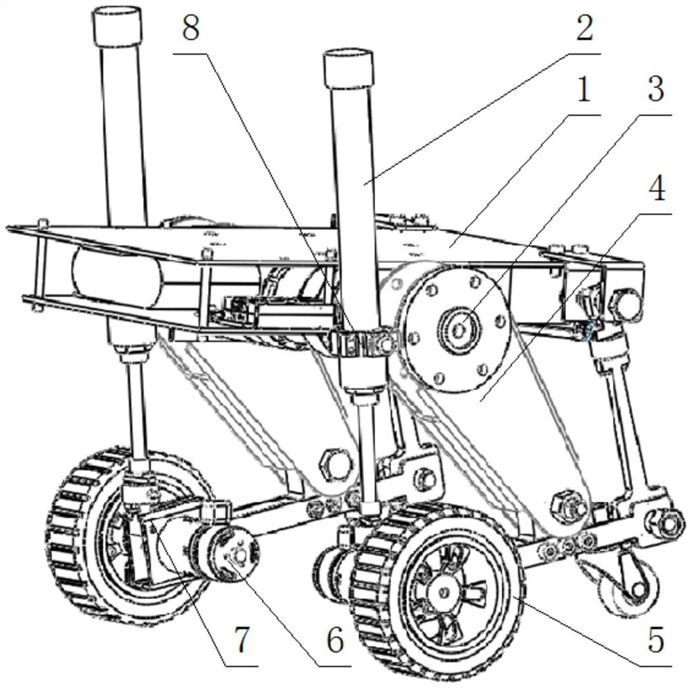
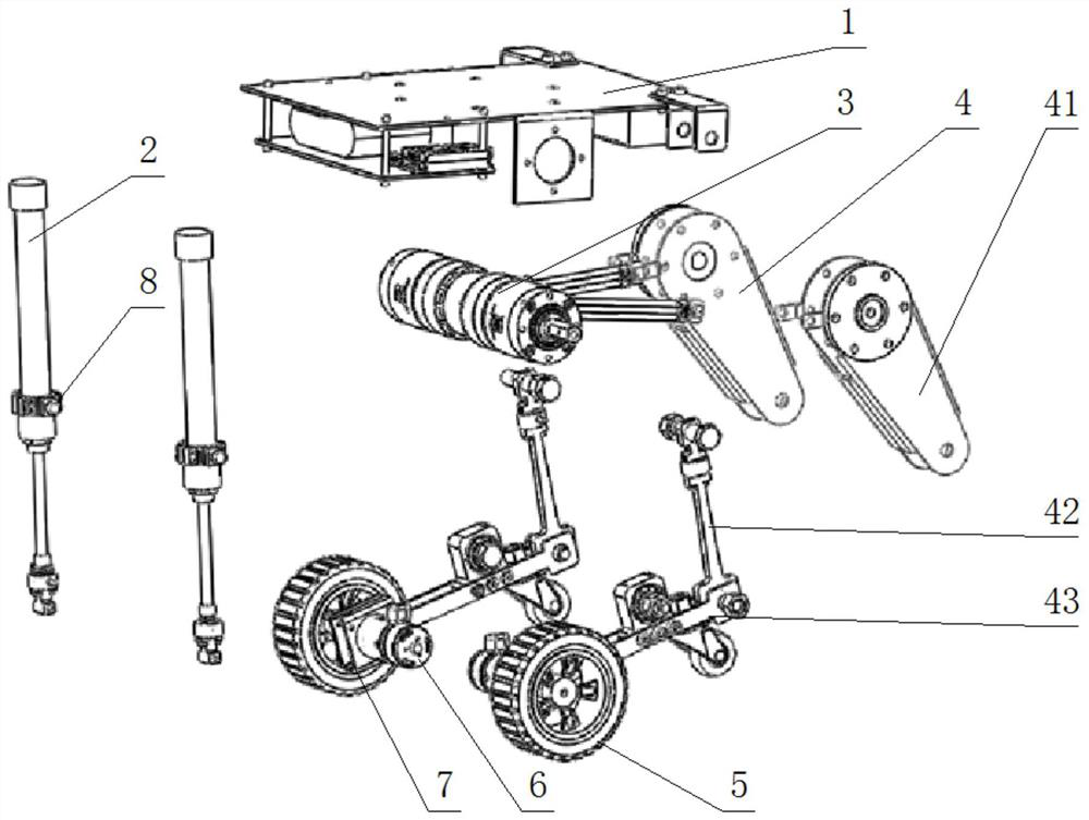
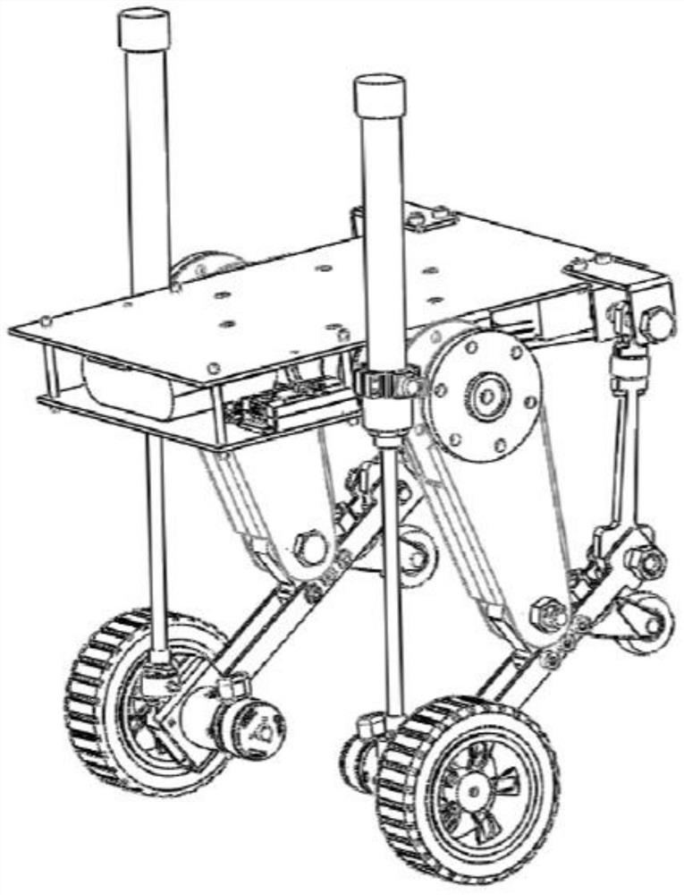
[0055] Such as Figure 1 to Figure 3 As shown, the walking system used for the walking device includes outriggers, and the outriggers include a linkage mechanism 4 and a drive rotation device 3 for driving the linkage mechanism 4 to expand and contract;
[0056] The link mechanism 4 is provided with a wheel frame 7 for installing the traveling wheel 5; it also includes a cylinder 2, and in both the cylinder part and the piston rod part of the cylinder 2, one of them is fixedly connected with the wheel frame 7, A connector 8 is fixed on the other;
[0057] The connecting piece 8 is provided with a rotating shaft, and the cylinder 2 can rotate around the rotating shaft;
[0058] The rotating shaft on the connecting member 8 is parallel to the rotating shaft axis on the link mechanism 4;
[0059] A locking piece is also provided on the connecting piece 8, and the locking piece is used to realize the rotation locking of the cylinder 2 relative to the rotating shaft.
[0060] In...
Embodiment 2
[0067] This embodiment is further optimized and refined on the basis of embodiment 1:
[0068] As a specific implementation of the link mechanism 4, it is set as follows: the link mechanism 4 includes a third link 43, a first link 41 and a second link 42, and the first link 41 and the second link 42 are all It is hingedly connected to different positions in the length direction of the third connecting rod 43 through a rotating shaft;
[0069] The driving device 3 is a joint driving motor connected to the first connecting rod 41 or the second connecting rod 42 . When the connecting rod mechanism 4 is applied to the walking device, the joint driving motor, as a low inertia, high response electric driving force source, can be installed on the frame 1, such as the driving and rotating device 3 is connected with the first connecting rod 41 , the second connecting rod 42 is hingedly connected with the frame 1, so that the four-bar linkage mechanism 4 is formed by the frame 1, the f...
Embodiment 3
[0071] This embodiment is further optimized and refined on the basis of embodiment 1:
[0072] To be more complete, in order to reduce the load of the running device when it runs autonomously, it is configured to: further include an air source device for providing a compressed air source for the cylinder 2, and the air source device is a compressed gas cylinder. When this solution is used in practice, the compressed gas cylinder provides compressed gas for the cylinder 2 through the gas circuit and corresponding gas circuit components, so that the pneumatic system including the gas source device and the cylinder 2 carried on the walking device has a light weight and a good structure. simple features.
PUM
 Abstract
Description
Claims
Application Information
 - R&D
- Intellectual Property
- Life Sciences
- Materials
- Tech Scout
- Unparalleled Data Quality
- Higher Quality Content
- 60% Fewer Hallucinations
Browse by: Latest US Patents, China's latest patents, Technical Efficacy Thesaurus, Application Domain, Technology Topic, Popular Technical Reports.
© 2025 PatSnap. All rights reserved.Legal|Privacy policy|Modern Slavery Act Transparency Statement|Sitemap|About US| Contact US: help@patsnap.com