Semi-grouting sleeve without steel bar connecting threaded holes

A semi-grouting sleeve and threaded hole technology, which is applied to structural elements, building components, building reinforcements, etc., can solve problems such as complex structures, achieve the effects of increasing area, improving stress conditions, and firm and convenient connections

Pending Publication Date: 2021-09-17
WUHAN YUANJIN BUILDING MATERIALS TECH CO LTD
View PDF3 Cites 0 Cited by
  • Summary
  • Abstract
  • Description
  • Claims
  • Application Information

AI Technical Summary

Problems solved by technology

The connecting structure includes a reinforced semi-grouting sleeve, upper prefabricated components and lower prefabricated components; the semi-grouting sleeve in this utility model needs to be provided with a snap-fit ​​structure at the end of the prefabricated end sleeve, and after the sleeve is connected, conventional welding operations are performed, and the structure more complex

Method used


Image

  • Semi-grouting sleeve without steel bar connecting threaded holes
  • Semi-grouting sleeve without steel bar connecting threaded holes
  • Semi-grouting sleeve without steel bar connecting threaded holes

Examples


Embodiment 1

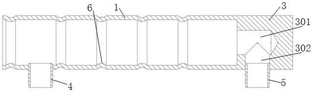
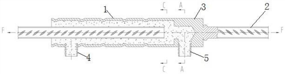
[0030] like figure 1 and figure 2 As shown, a half-grouting sleeve without steel bar connecting threaded holes, including a half-grouting sleeve grouting section 1, a half-grouting sleeve steel connection section 3, a grouting nozzle 4 and a grouting nozzle 5, and the half-grouting sleeve grouting section The outer periphery of 1 is provided with the grouting nozzle 4; the semi-grouting sleeve reinforcement connecting section 3 is provided with an axial blind hole 301 and a radial grouting hole 302, and the axial blind hole 301 and the radial row The slurry holes 302 are arranged vertically and through each other, and the slurry discharge nozzle 5 is arranged at the radial slurry discharge holes 302 . The inner diameters of the axial blind hole 301 and the radial slurry discharge hole 302 are set to be the same.

[0031] The present invention cancels the thread of the half-grouting sleeve part connected with the reinforcing bar, and uses it as the blind hole end of the rein...

Embodiment 2

[0043] In this embodiment, the dangerous section at the pulp discharge is analyzed.

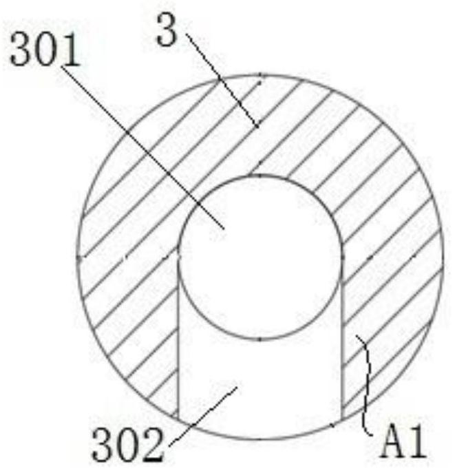
[0044] like figure 2 and image 3 As shown, taking a steel pipe with an outer diameter of 40 mm and a wall thickness of 3 mm as an example, the prepared semi-grouting sleeve grouting section 1 has an outer diameter of 40 mm and a wall thickness of 3 mm. The connection setting of the semi-grouting sleeve steel bar connecting section 3 of the grouting hole 302, the diameters of the axial blind hole 301 and the radial grouting hole 302 are both 18 mm, and the dangerous section is A-A under the action of the tension F, which is located in the half-grouting sleeve On the connection section 3 of the steel bar, the area of ​​the dangerous section is A1.

[0045] like figure 2 and Image 6 As shown, under the action of tension F, the dangerous cross-section C-C, the cross-sectional area is A3.

[0046] like Figure 4 and Figure 5 As shown, the half-grouting sleeve is a conventional structur...


PUM


Abstract

The invention discloses a semi-grouting sleeve without steel bar connecting threaded holes. The semi-grouting sleeve comprises a semi-grouting sleeve grouting section, a semi-grouting sleeve steel bar connecting section, a grouting nozzle and a slurry discharging nozzle, wherein the grouting nozzle is arranged on the periphery of the semi-grouting sleeve grouting section, the end of the semi-grouting sleeve steel bar connecting section is closed and provided with an axial blind hole and a radial slurry discharging hole, the axial blind hole and the radial slurry discharging hole are perpendicular to each other and are arranged in a penetrating mode, and the slurry discharging nozzle is arranged at the position of the radial slurry discharging hole. According to the semi-grouting sleeve, the area of the dangerous section is increased, so that the tensile strength of the dangerous section is improved; the slurry discharging hole is are formed in the blind hole end, so that the semi-grouting sleeve is safe and reliable; and the semi-grouting sleeve is simple in structure, reasonable in stress and firm and convenient and fast in steel bar connection.

Description

technical field [0001] The invention relates to the technical field of construction industry, in particular to a semi-grouting sleeve without steel bar connecting threaded holes. Background technique [0002] The grouting sleeve for steel bar connection is widely used in prefabricated residential concrete components, and is an important part for connecting on-site steel bars. The use of the grouting sleeve greatly improves the construction efficiency and saves time, manpower, and site costs. The half-grouting sleeve is one of the types. The traditional half-grouting sleeve is provided with threaded holes for connecting steel bars, and the processing cost is high and the efficiency is low. [0003] For example, the Chinese utility model patent (publication number: CN208251467U) disclosed a roll-formed steel half-grouting sleeve and its connection structure in 2018. The steel half-grouting sleeve is composed of an assembly end sleeve and a prefabricated end sleeve. The outer ...

Claims


Application Information

Patent Timeline
Patent Type & Authority Applications(China)
IPC IPC(8): E04C5/16
CPCE04C5/165
Inventor 陈鲲李丽娜
Owner WUHAN YUANJIN BUILDING MATERIALS TECH CO LTD
Why Eureka
Try Eureka