Self-adaptive power vibration reduction gear

A dynamic vibration reduction and self-adaptive technology, applied in belts/chains/gears, components with teeth, transmission parts, etc., can solve the problem that gears cannot increase the frequency of vibration reduction

Pending Publication Date: 2021-09-17
CHANGZHOU INST OF TECH
View PDF0 Cites 2 Cited by
  • Summary
  • Abstract
  • Description
  • Claims
  • Application Information

AI Technical Summary

Problems solved by technology

[0004] In order to solve the problem that the current gear cannot automatically adapt to the frequency of vibration reduction according to the increase of the system speed, the invention provides an adaptive dynamic vibration reduction gear, including a gear with several vibration reduction modules embedded in the gear. The damping module includes a damping mass, a centrifugal mass, an upper spring and a lower spring, the gear is provided with a mounting groove, and the damping mass is fixed in the mounting groove, and the damping mass is fixed in the mounting groove. One side of the connecting rod is also fixed with a connecting rod, the other end of the connecting rod is fixed in the installation groove, the centrifugal mass slides on the connecting rod, the two sides of the centrifugal mass are respectively provided with the upper spring and a lower spring, and the upper spring and the lower spring are sleeved on the connecting rod, one end of the upper spring is against the damping mass, the other end is against the centrifugal mass, and one end of the lower spring is against the centrifugal mass, and the other end against the bottom of the mounting groove

Method used


Image

  • Self-adaptive power vibration reduction gear
  • Self-adaptive power vibration reduction gear
  • Self-adaptive power vibration reduction gear

Examples


Embodiment 1

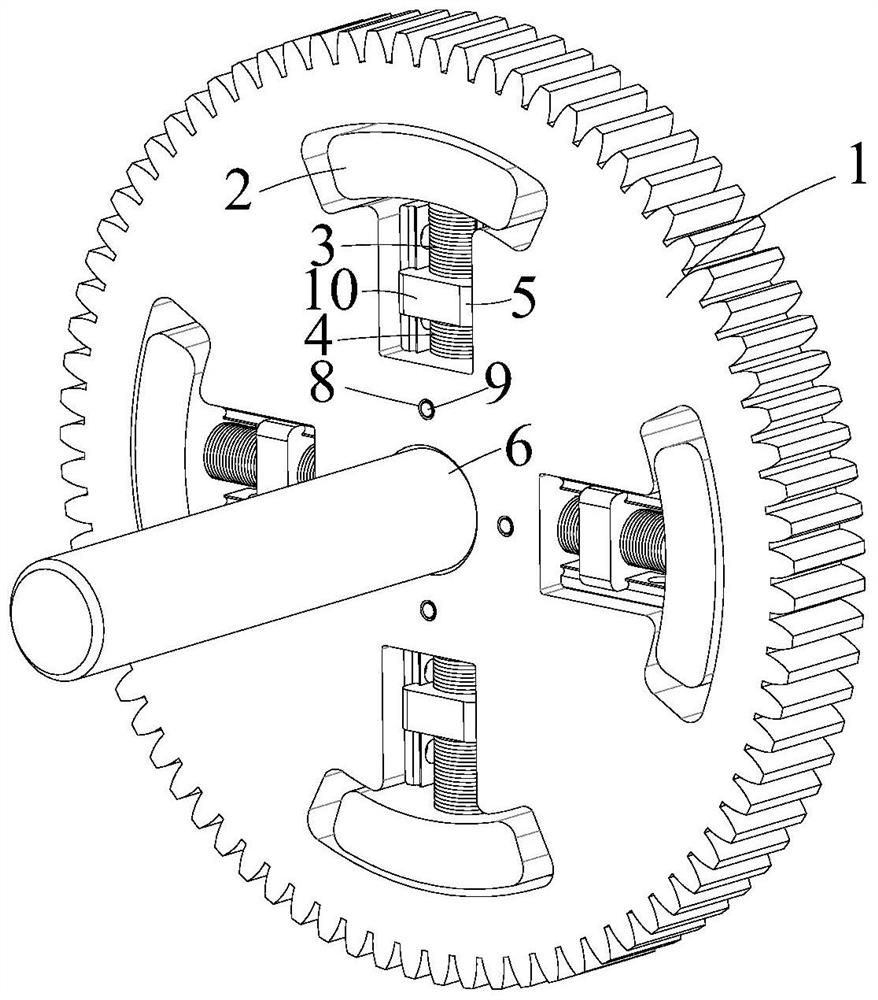
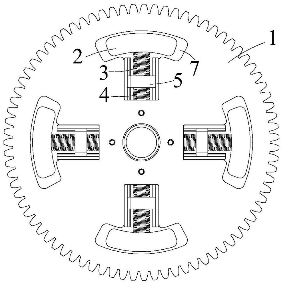
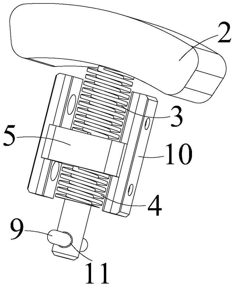
[0017] An adaptive dynamic damping gear, including a gear 1, the gear 1 is embedded with several damping modules, and the damping modules include a damping mass 2, an centrifugal mass 5, an upper spring 3 and a lower spring 4 , the gear 1 is provided with a mounting groove 7, the vibration-damping mass 2 is fixed in the mounting groove 7, a connecting rod is fixed on one side of the vibration-damping mass 2, and the other end of the connecting rod Fixed in the installation groove 7, the centrifugal mass 5 slides on the connecting rod, the upper spring 3 and the lower spring 4 are respectively provided on both sides of the centrifugal mass 5, and the upper spring 3 and the lower spring 4 are both sleeved on the connecting rod, one end of the upper spring 3 is against the damping mass 2, the other end is against the centrifugal mass 5, and one end of the lower spring 4 is against the centrifugal mass 5. The other end of the mass block 5 is against the bottom of the installation ...


PUM


Abstract

The invention relates to a self-adaptive power vibration reduction gear. The gear comprises a gear body, a plurality of vibration reduction modules are embedded in the gear body, each vibration reduction module comprises a vibration reduction mass block, a centrifugal mass block, an upper spring and a lower spring, mounting grooves are formed in the gear body, the vibration reduction mass blocks are fixed in the mounting grooves, connecting rods are further fixed to one sides of the vibration reduction mass blocks, the other ends of the connecting rods are fixed in the mounting grooves, the centrifugal mass blocks slide on the connecting rods, the upper springs and the lower springs are arranged on two sides of the centrifugal mass blocks respectively, the connecting rods are connected to the upper springs and the lower springs in a sleeving mode, one ends of the upper springs abut against the vibration reduction mass blocks, the other ends of the upper springs abut against the centrifugal mass blocks, one ends of the lower springs abut against the centrifugal mass blocks, and the other ends abut against the bottoms of the mounting grooves. According to the gear, in the power transmission process of the gear body, the purpose of self-adaptive vibration and noise reduction can be achieved within a certain rotating speed range, the rotating speed is not limited to a certain fixed rotating speed any more, and the purpose of vibration and noise reduction is achieved under the condition that the appearance and the space size of the gear are not increased.

Description

technical field [0001] The invention relates to the technical field of gears, in particular to an adaptive dynamic damping gear. Background technique [0002] The gear system transmits power through the meshing of gear teeth. During the transmission process, when the speed approaches or reaches the natural frequency of the system, the system will generate severe vibration and noise, and the life of the system will be significantly reduced or even directly broken. [0003] In order to solve this type of problem, various damping gears have appeared now, including adding damping pins inside the gears, increasing rubber damping layers and increasing dynamic shock absorbers and other damping measures. The method of adding damping pins and damping layers inside the gear has a certain effect, but the effect is limited for the working condition where the working speed is near the resonance frequency of the system. By adding a dynamic shock absorber, the vibration of the speed condi...

Claims


Application Information

Patent Timeline
Patent Type & Authority Applications(China)
IPC IPC(8): F16H55/14F16H55/17F16F15/14F16H57/00
CPCF16H55/14F16H55/17F16F15/1421F16H57/0018
Inventor 盛冬平陆凤霞鲍和云徐红丽胡少刚何亚峰门艳忠
Owner CHANGZHOU INST OF TECH
Why Eureka
Try Eureka