Deep independent soil monitoring and sampling device

A soil monitoring and sampling device technology, applied in the direction of sampling devices, etc., can solve the problems of confusing shallow sample soil and deep sample soil, troublesome sampling work, time-consuming and labor-intensive work, etc., to improve convenience, facilitate transportation and transfer, and sample working simple effect

Inactive Publication Date: 2021-09-17
INST OF MOUNTAIN HAZARDS & ENVIRONMENT CHINESE ACADEMY OF SCI
View PDF5 Cites 0 Cited by
  • Summary
  • Abstract
  • Description
  • Claims
  • Application Information

AI Technical Summary

Problems solved by technology

We will use soil sampling devices to understand some soil pollution situations, but we will encounter some problems when using sampling devices. For example, some sampling devices can only sample shallow soil when using them. For deeper or profile Layered soil sampling is time-consuming and laborious. At the same point, the shallow layer must be sampled first, and then the deep soil sampled. It is difficult to sample the deep soil separately. The sampling work is very troublesome, and it is easy to confuse the shallow sample soil with the deep layer. sample soil

Method used


Image

  • Deep independent soil monitoring and sampling device
  • Deep independent soil monitoring and sampling device
  • Deep independent soil monitoring and sampling device

Examples


Embodiment 1

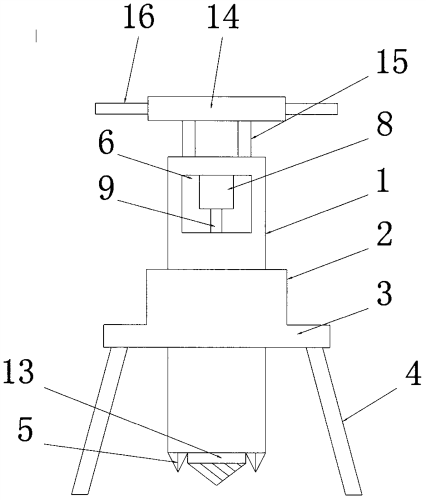
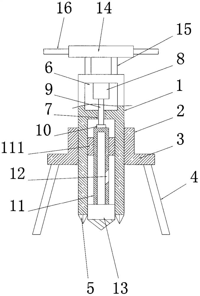
[0020] See Figure 1-2 , a deep independent soil monitoring and sampling device, comprising a lifting cylinder 1, the lifting cylinder 1 is a cylindrical structure with an open bottom, the bottom of the lifting cylinder 1 is evenly provided with a number of soil-breaking teeth 5, the upper part of the lifting cylinder 1 A power chamber 6 is provided, and the power chamber 6 is connected to the inner cavity of the lifting cylinder 1 through the through hole 7. The inner cavity top wall of the power chamber 6 is fixedly connected to the hydraulic cylinder 8, and the bottom of the telescopic rod 9 on the hydraulic cylinder 8 The end passes through the through hole 7 and is connected with the sampling cylinder 11 matched with the lifting cylinder 1 through the rotation of the bearing seat 10. The bottom end of the sampling cylinder 11 is fixedly connected with the soil breaking cone 13 matched with the lifting cylinder 1. One end of one side is connected to the sampling hole 12. T...

Embodiment 2

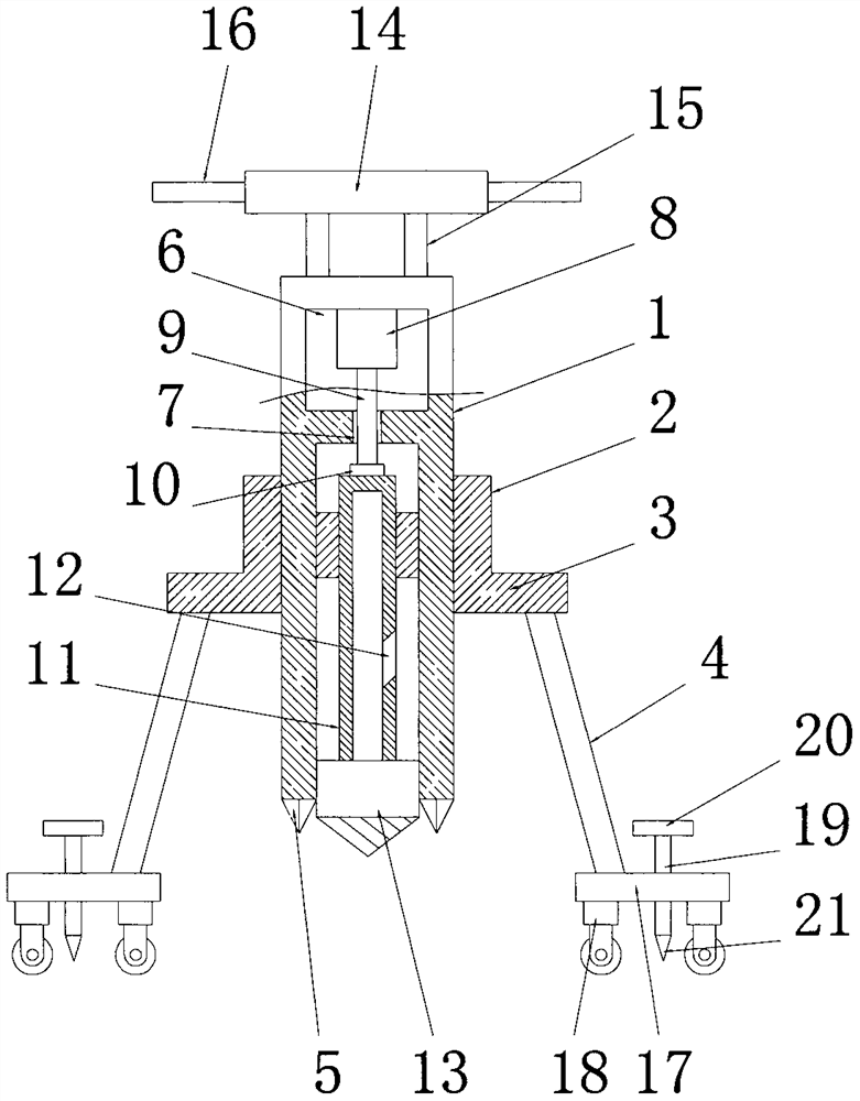
[0022] See Figure 3-4 The difference from Example 1 is that the bottom end of the leg 4 is fixedly connected to the foot plate 17, the foot plate 17 is a disc plate structure, and the bottom end of the foot plate 17 is provided with a number of universal wheels 18 in a circular array. , the universal wheel 18 is equipped with a foot brake, and the universal wheel 18 is used to cooperate with the stirring 17 and the legs 4 to support the whole device, which is convenient for the transportation and transfer of the whole device, and can greatly improve the convenience of the device in the field.

[0023] The middle part of described foot plate 17 is embedded with fixed screw rod 19, is threaded connection between foot plate 17 and fixed screw rod 19, and described fixed screw rod 19 is located between all universal wheels 18, and the bottom end of fixed screw rod 19 is fixedly connected and fixed. Anchor thorn 21, the top of fixed screw rod 19 is fixedly connected to control pan...


PUM


Abstract

The invention discloses a deep independent soil monitoring and sampling device. The device comprises a lifting cylinder, a power cavity is formed in the upper portion of the lifting cylinder and is in through connection with an inner cavity of the lifting cylinder through a through hole, and the top wall of the inner cavity of the power cavity is fixedly connected with a hydraulic cylinder. The bottom end of a telescopic rod on the hydraulic cylinder penetrates through the through hole and is rotationally connected with a sampling barrel matched with the lifting barrel through a bearing seat; the bottom end of the sampling barrel is fixedly connected with a soil breaking cone matched with the lifting barrel; one side end of the sampling barrel is connected with the sampling hole in a penetrating manner, and the outer side of the sampling barrel is sleeved with a pushing sleeve matched with the lifting barrel; the pushing sleeve is in threaded connection with the lifting cylinder, a rotating disc is arranged above the lifting cylinder and fixedly connected with the lifting cylinder through a plurality of connecting rods, and a plurality of handles are evenly arranged on the outer circle face of the rotating disc. The whole sampling work is very simple, wherein the deep soil can be directly and independently sampled, so that the quality of a soil sample can be ensured, and the accuracy of later detection and analysis is ensured.

Description

technical field [0001] The invention relates to the technical field of soil sampling, in particular to a deep independent soil monitoring and sampling device. Background technique [0002] Soil pollutants can be roughly divided into two categories: inorganic pollutants and organic pollutants. Inorganic pollutants mainly include acids, alkalis, heavy metals, salts, compounds of radioactive elements cesium and strontium, compounds containing arsenic, selenium and fluorine, etc. Organic pollutants mainly include organic pesticides, phenols, cyanides, petroleum, synthetic detergents, 3,4-benzopyrene, and harmful microorganisms brought by urban sewage, sludge, and manure. When there are too many harmful substances in the soil and exceed the self-purification capacity of the soil, the composition, structure and function of the soil will change, the microbial activities will be inhibited, and the harmful substances or their decomposition products will gradually accumulate in the s...

Claims


Application Information

Patent Timeline
Patent Type & Authority Applications(China)
IPC IPC(8): G01N1/08
CPCG01N1/08
Inventor 高美荣况福虹章熙锋王艳强
Owner INST OF MOUNTAIN HAZARDS & ENVIRONMENT CHINESE ACADEMY OF SCI
Why Eureka
Try Eureka