
Light beam shaping method, device, system, storage medium and electronic device

A beam, flat-top beam technology, applied in the optical field, can solve the problem of large beam energy loss, and achieve the effect of solving the large beam energy loss

Active Publication Date: 2022-01-11
WUHAN RAYCUS FIBER LASER TECHNOLOGY CO LTD
View PDF6 Cites 0 Cited by
  • Summary
  • Abstract
  • Description
  • Claims
  • Application Information

AI Technical Summary

Problems solved by technology

[0005] Embodiments of the present invention provide a beam shaping method, device, system, storage medium, and electronic device, so as to at least solve the problem of large beam energy loss in the beam shaping process in the related art

Method used


Image

  • Light beam shaping method, device, system, storage medium and electronic device
  • Light beam shaping method, device, system, storage medium and electronic device
  • Light beam shaping method, device, system, storage medium and electronic device

Examples


Embodiment Construction

[0024] Embodiments of the present invention will be described in detail below with reference to the drawings and in combination with the embodiments.

[0025] It should be noted that the terms "first" and "second" in the description and claims of the present invention and the above drawings are used to distinguish similar objects, but not necessarily used to describe a specific sequence or sequence.

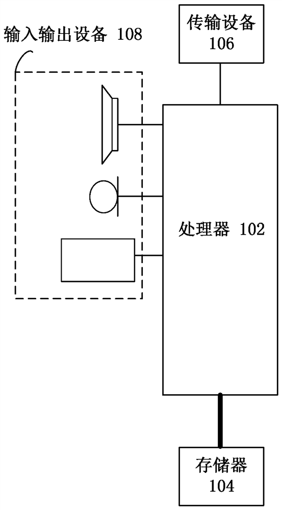
[0026] The method embodiments provided in the embodiments of the present invention may be executed in mobile terminals, computer terminals or similar computing devices. Taking running on a mobile terminal as an example, figure 1 It is a block diagram of the mobile terminal hardware structure of the light beam shaping method according to the embodiment of the present invention. Such as figure 1 Shown, the mobile terminal can include one or more ( figure 1 Only one is shown in ) processor 102 (processor 102 may include but not limited to processing devices such as microprocessor...


PUM


Abstract

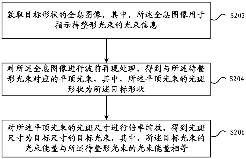
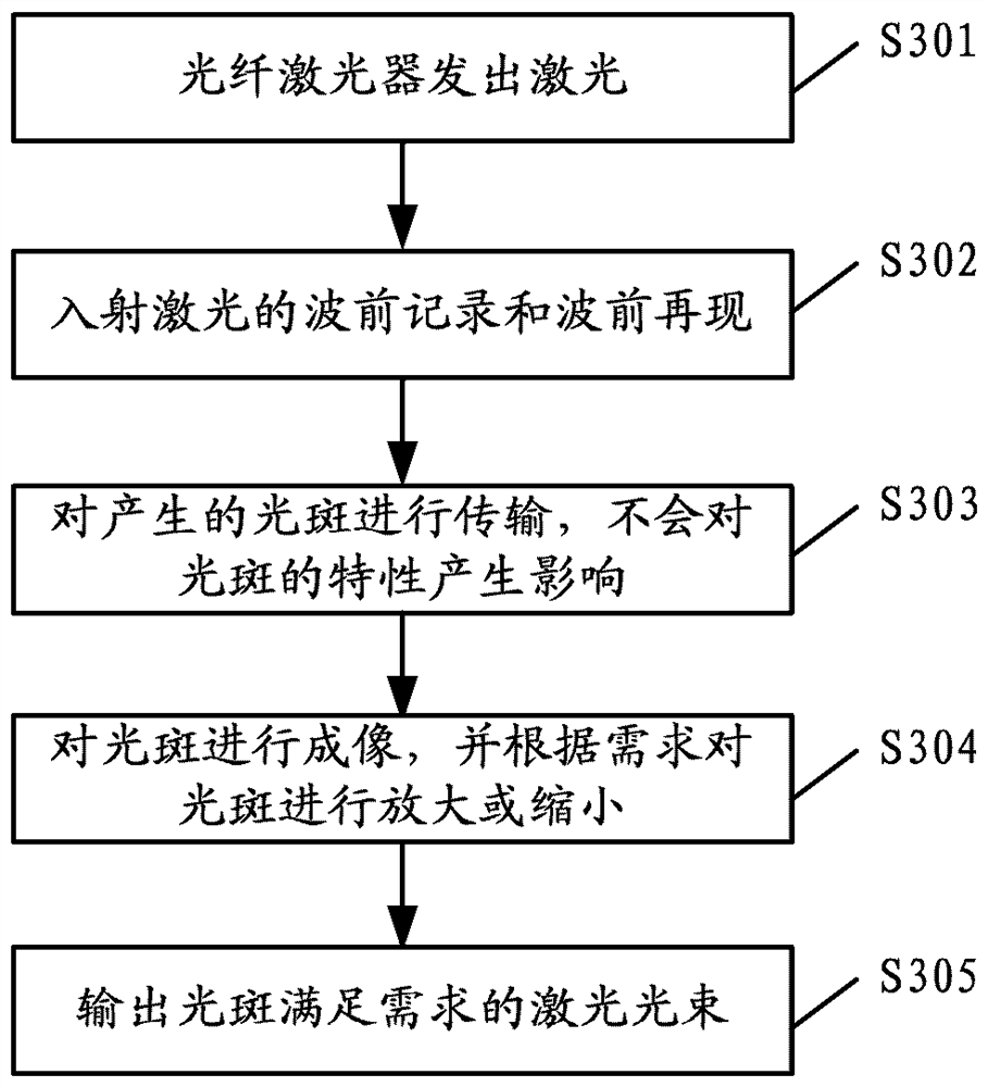
Embodiments of the present invention provide a light beam shaping method, device, system, storage medium, and electronic device, wherein the method includes: acquiring a holographic image of a target shape, wherein the holographic image is used to indicate light wave information of the light beam to be shaped; Perform wavefront reconstruction processing on the holographic image to obtain a flat-hat beam corresponding to the beam to be shaped, wherein the spot shape of the flat-hat beam is the target shape; scale the spot size of the flat-hat beam to obtain a spot size equal to the target size A target beam, wherein the beam energy of the target beam is equal to the beam energy of the beam to be shaped. The present invention solves the problem of large beam energy loss in the beam shaping process in the related art, and further achieves the effect of reducing the beam energy loss in the beam shaping process.

Description

technical field [0001] Embodiments of the present invention relate to the field of optics, and in particular, to a light beam shaping method, device, system, storage medium, and electronic device. Background technique [0002] With the vigorous development of optical communication technology, the precision requirements of industrial precision processing technology are getting higher and higher. Technologies such as laser display and laser imaging have entered thousands of households. Fiber laser technology is playing an increasingly important role in all walks of life. effect. At the same time, the spatial shape distribution of the laser beam output by the laser has higher requirements. Usually, the energy of the laser beam output by the laser is approximately Gaussian in spatial form, which is called Gaussian distribution. However, the Gaussian distributed beam cannot meet some special requirements in practical applications. For example, in some practical applications, th...

Claims


Application Information

Patent Timeline
Patent Type & Authority Patents(China)
IPC IPC(8): G06T5/00G06T3/40G02B27/09
CPCG06T5/00G06T3/40G02B27/0944
Inventor 阮仁秋张鑫涵倪蒙夏巨江朱超刘晓旭闫大鹏
Owner WUHAN RAYCUS FIBER LASER TECHNOLOGY CO LTD
Learn More