
A monitoring system and method for a photovoltaic power converter in an optical fiber power supply system

A power converter and power supply system technology, applied in the monitoring of photovoltaic systems, photovoltaic modules, photovoltaic power generation, etc., to achieve the effects of load capacity testing, accurate positioning, and improved reliability

Active Publication Date: 2021-11-02
成都金迈微科技有限公司
View PDF19 Cites 0 Cited by
  • Summary
  • Abstract
  • Description
  • Claims
  • Application Information

AI Technical Summary

Problems solved by technology

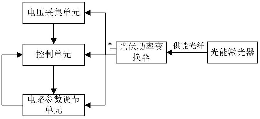
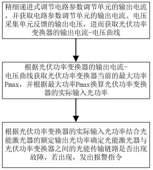
[0004] The purpose of the present invention is to overcome the problem that the optical energy transmission link between the photovoltaic power converter and the laser cannot be determined online in the prior art and provides a monitoring system and method for the photovoltaic power converter in the optical fiber power supply system. The actual input optical power of the photovoltaic power converter is obtained by online scanning and monitoring of the maximum output power of the photovoltaic power converter, and the optical power between the optical laser and the photovoltaic power converter is judged in combination with the rated output optical power of the photovoltaic power converter. Whether the transmission link is faulty, so as to protect the photovoltaic power converter

Method used


Image

  • A monitoring system and method for a photovoltaic power converter in an optical fiber power supply system
  • A monitoring system and method for a photovoltaic power converter in an optical fiber power supply system
  • A monitoring system and method for a photovoltaic power converter in an optical fiber power supply system

Examples


Embodiment Construction

[0037] The technical solutions of the present invention will be clearly and completely described below in conjunction with the accompanying drawings. Apparently, the described embodiments are part of the embodiments of the present invention, but not all of them. Based on the embodiments of the present invention, all other embodiments obtained by persons of ordinary skill in the art without making creative efforts belong to the protection scope of the present invention.

[0038] In the description of the present invention, it should be noted that the terms belonging to "center", "upper", "lower", "left", "right", "vertical", "horizontal", "inner", "outer" etc. The indicated direction or positional relationship is based on the direction or positional relationship described in the drawings, and is only for the convenience of describing the present invention and simplifying the description, rather than indicating or implying that the referred device or element must have a specific ...


PUM


Abstract

The invention discloses a monitoring system and method for a photovoltaic power converter in an optical fiber power supply system, which belongs to the technical field of optical fiber power supply, and includes a control unit, a circuit parameter adjustment unit and a voltage acquisition unit; the control unit adjusts and acquires photovoltaic power through the circuit parameter adjustment unit The output current of the power converter, the output voltage of the photovoltaic power converter is obtained through the voltage acquisition unit, and then the current maximum output power of the photovoltaic power converter is obtained, and the actual input optical power of the photovoltaic power converter is converted to determine the light energy transmission chain Whether there is a fault in the road, so as to ensure the normal and stable operation of the system. The control unit judges the relationship between the rated current of the post-stage equipment and the current that the photovoltaic power converter can provide, and can predict whether the post-stage equipment will overload the photovoltaic power converter. If so, the photovoltaic power converter is not allowed to supply power to the post-stage equipment. Avoid greatly shortened service life or permanent damage of photovoltaic power converter.

Description

technical field [0001] The invention relates to the technical field of optical fiber power supply, in particular to a monitoring system and method for a photovoltaic power converter in an optical fiber power supply system. Background technique [0002] The optical fiber power supply system transmits the light energy generated by the high-power laser to the photovoltaic power converter through the optical fiber, and the photovoltaic power converter converts the light energy into electrical energy to supply power to the subsequent equipment. Since the optical fiber power supply system is often affected by the bending of the optical fiber or the good contact of the optical fiber connector, the optical power entering the photovoltaic power converter is easily insufficient, resulting in insufficient output power of the photovoltaic power converter. The device is overloaded. Secondly, optical fiber power supply systems are mostly used in high-voltage or complex and strong electro...

Claims


Application Information

Patent Timeline
Patent Type & Authority Patents(China)
IPC IPC(8): H02J50/30H02S50/00H02H9/02
CPCH02J50/30H02S50/00H02H9/02Y02E10/50
Inventor 王波张洪妹王照
Owner 成都金迈微科技有限公司
Learn More