Rotating electric machine unit

A technology of rotating motors and rotating speeds, applied in the direction of motors, electrical components, electromechanical devices, etc., can solve the problems of output performance reduction and achieve the effect of suppressing the reduction of output efficiency

Pending Publication Date: 2021-09-17
HONDA MOTOR CO LTD
View PDF1 Cites 0 Cited by
  • Summary
  • Abstract
  • Description
  • Claims
  • Application Information

AI Technical Summary

Problems solved by technology

Furthermore, if the rotating electrical machine becomes too hot due to heat generation, demagnetization of the permanent magnets and the like will occur, resulting in a decrease in output performance.

Method used


Image

  • Rotating electric machine unit
  • Rotating electric machine unit
  • Rotating electric machine unit

Examples


Embodiment Construction

[0051] Hereinafter, an embodiment of the rotating electric machine unit 1 of the present invention will be described based on the drawings.

[0052]

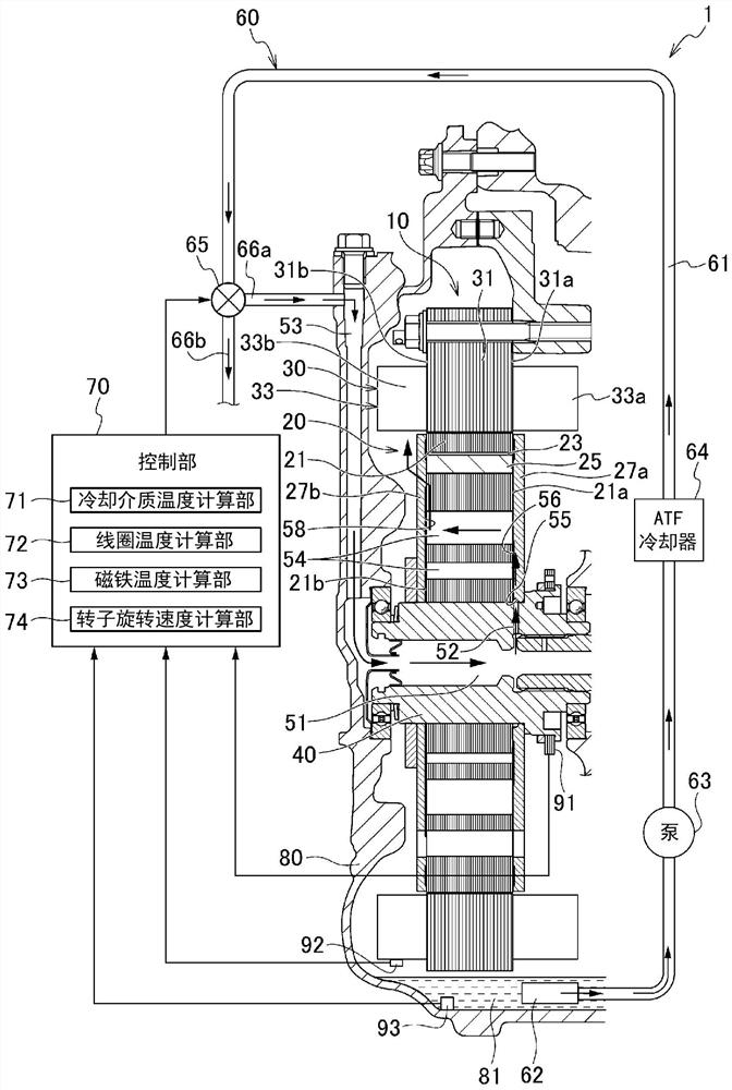
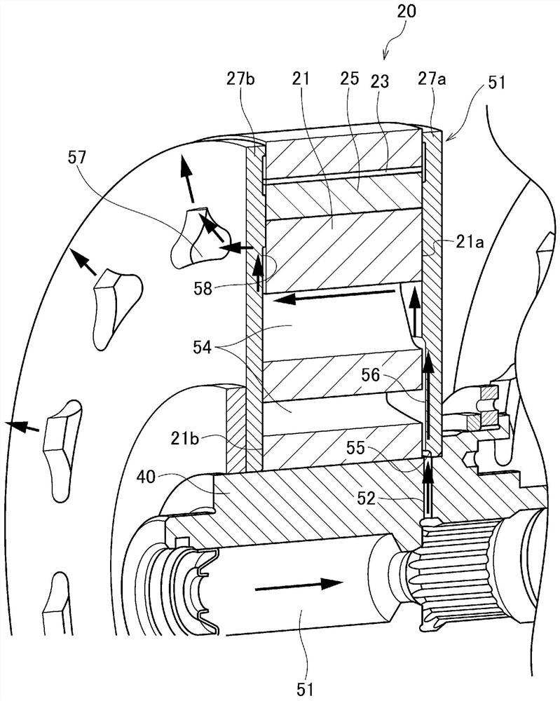
[0053] Such as figure 1 and figure 2 As shown, the rotary electric machine unit 1 of this embodiment includes: a rotary electric machine 10 having a rotor 20 and a stator 30 ; a rotor shaft 40 ; and a cooling medium supply device 60 . The rotating electrical machine 10 and the rotor shaft 40 are accommodated in a housing 80 .

[0054] In addition, in this specification etc., when referring to an axial direction, a radial direction, and a circumferential direction, it means the direction based on the rotation axis of the rotary electric machine 10. In addition, the axially inner side refers to the central side of the rotating electric machine 10 in the axial direction, and the axially outer side refers to a side away from the center of the rotating electric machine 10 in the axial direction.

[0055] The rotor shaft 40 is a...


PUM


Abstract

The present invention provides a rotating electric machine unit capable of suppressing a decrease in output efficiency of a rotating electric machine without decreasing the cooling efficiency of the rotating electric machine. The rotating electric machine unit includes: a rotating electric machine; a rotor shaft in which a cooling medium flow path is provided; and a cooling medium supply device that supplies a cooling medium to the cooling medium flow path. The cooling medium passing through the cooling medium flow path is supplied to the rotor and the stator of the rotating electric machine to cool the rotating electric machine. The cooling medium supply device is provided with: a switching unit that switches between an axial cooling implementation state in which the cooling medium is supplied to the cooling medium flow path and an axial cooling stop state in which the cooling medium is not supplied to the cooling medium flow path; and a control unit that controls the switching unit. When the cooling medium temperature calculated by the cooling medium temperature calculation unit is a temperature within a predetermined cooling medium temperature range, the control unit controls the switching unit so that the axial cooling is stopped.

Description

technical field [0001] The present invention relates to a rotating electrical machine unit mounted on an electric vehicle or the like. Background technique [0002] Conventionally, rotating electric machines such as electric motors and generators are mounted on electric vehicles such as hybrid vehicles, battery-driven vehicles, and fuel cell vehicles. In recent years, high torque and high output of rotating electric machines mounted on electric vehicles have been promoted. A rotating electrical machine generates losses such as copper loss, iron loss, and mechanical loss due to driving, and generates heat due to these losses. Therefore, the higher the torque and the higher the output, the higher the amount of heat generated. Furthermore, when the rotating electrical machine becomes too high in temperature due to heat generation, demagnetization of permanent magnets or the like occurs, resulting in a decrease in output performance. [0003] Therefore, further improvement in ...

Claims


Application Information

Patent Timeline
Patent Type & Authority Applications(China)
IPC IPC(8): H02K9/193H02K9/00H02K7/00H02K1/32H02K3/24
CPCH02K9/193H02K7/003H02K1/32H02K3/24Y02T10/64
Inventor 平西亨佐藤哲
Owner HONDA MOTOR CO LTD
Why Eureka
Try Eureka