
An automobile pedal positioning welding device

A technology of positioning welding and automobile pedals, which is applied in welding equipment, auxiliary equipment, auxiliary welding equipment, etc., can solve the problems of inability to achieve comprehensive welding, and achieve the effects of avoiding manual repair welding, avoiding slag inclusion, and saving manpower

Active Publication Date: 2021-11-02
佛山昱希汽车科技有限公司
View PDF0 Cites 0 Cited by
  • Summary
  • Abstract
  • Description
  • Claims
  • Application Information

AI Technical Summary

Problems solved by technology

[0003] In order to overcome the disadvantages that when the pedal and the pedal arm are welded in a circular manner, full-scale welding cannot be realized, there is a gap, and manual or precision control equipment is required for repair welding, the invention provides a positioning welding device for automobile pedals

Method used


Image

  • An automobile pedal positioning welding device
  • An automobile pedal positioning welding device
  • An automobile pedal positioning welding device

Examples


Embodiment 1

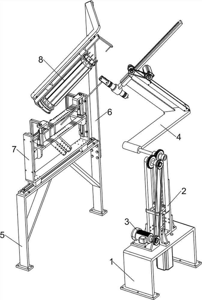
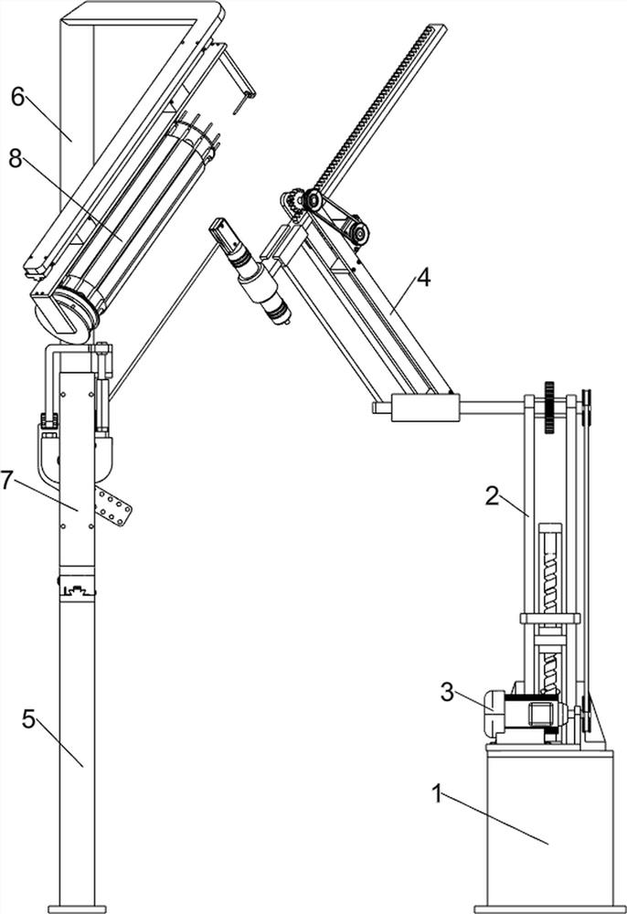
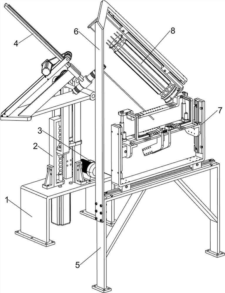
[0034] Car pedal positioning welding device, such as Figure 1-4 As shown, including the first mounting frame 1, the lifting assembly 2, the first rotating assembly 3 and the welding mechanism 4; the rear portion of the first mounting frame 1 is connected to the lifting assembly 2; the first mounting frame 1 front connection has the first A rotating assembly 3, and the first rotating assembly 3 is connected to the lifting assembly 2; the upper portion of the lifting assembly 2 is connected to the welding mechanism 4, the welding mechanism 4 is used to weld the pedal and the pedal arm.

[0035] When using a car pedal to position the welding device, first install the debugging, then turn on the power, manually will be used for car brakes, clutches and throttles, and are located in the work area of ​​the welding mechanism 4, this The pedal and the pedal arm welded portion are brought together, the pedal is vertically placed, the pedal arm is facing down, and then controls the first ro...

Embodiment 2

[0037] On the basis of Example 1, if Figure 5 , Figure 7 with Figure 8 As shown, the welding mechanism 4 includes a fixing sleeve 401, a second connecting plate 402, a third connecting plate 403, a guide rail 404, a slide plate 411, a soldering torch 413, a first pinch plate 414, a curved groove 414a, a semi-circular hole groove 414b. The second pinch plate 415 and the electrode 416; the upper portion of the lifting assembly 2 is fixedly connected to the fixing sleeve 401; the rear side of the fixing sleeve 401 is fixedly connected to the second connecting plate 402; the second connecting plate 402 has a third connection. Board 403; the tip of the third connecting plate 403 is welded with guide slide rail 404; the guide rail 404 slides to be connected to the slide 411; the bottom portion of the slide plate 411 is fixedly connected to the solder torch 413; the upper portion of the solder torch 413 is fixedly connected to the first pinch plate 414; first pinch plate The clamping sur...


PUM


Abstract

The invention relates to a welding device, in particular to an automobile pedal positioning welding device. The technical problem to be solved is: when the pedal and the pedal arm are welded in a circular manner, full welding cannot be realized, and there is a gap, which needs to be repaired by manual or precision control equipment. The technical embodiment of the present invention is: an automobile pedal positioning welding device, including a lifting assembly, a first rotating assembly, a welding mechanism, etc.; a lifting assembly is connected to the rear part above the first mounting frame; There is a first rotating assembly, and the first rotating assembly is connected with the lifting assembly. The invention can automatically weld the pedal and the pedal arm, and at the same time, when the pedal and the pedal arm are welded circularly, the gap generated during the circular welding can be transferred to the side of the pedal arm, so that the gap can be repaired directly to obtain a complete circular welding To avoid manual repair welding, it is dangerous and will damage the eyes.

Description

Technical field [0001] The present invention relates to a welding apparatus, and more particularly to a car pedal positioning welding device. Background technique [0002] The pedal, the clutch and the pedal and the pedal arm are welded, and when the part of the pedal arm is connected to the pedal, it is necessary to carry out annular welding, and the pedal welding of the car brake, clutch and throttle and pedal arm Due to the presence of the pedal arm, use the existing equipment to ring welding, there will be a gap that cannot be welded, resulting in insufficient strength after the welding, the welding space is easily accumulated, and the welding area is rust, so it is necessary to manually It is completed to reduce the gap, or have a complex control complex. Inventive content [0003] In order to overcome the pedal and the pedal arm ring welding, it is unable to achieve full welding, there is a gap, and the disadvantage of manual or precision control equipment is required, and...

Claims


Application Information

Patent Timeline
Patent Type & Authority Patents(China)
IPC IPC(8): B23K37/00B23K37/04
CPCB23K37/00B23K37/0443
Inventor 洪苹果李玉华刘昱龙
Owner 佛山昱希汽车科技有限公司
Learn More